
Specify PET blowing cooling by separating the mold temperature-control requirement from the protection of the preform neck during heating. Define the required temperatures, flow, pressure, heat load, water quality, and control points for each circuit. Confirm performance at the machine under production conditions; a chiller nameplate or a cold supply pipe is not sufficient evidence.
Why Are Mold Cooling and Neck Protection Different?
The bottle body is stretched and formed after reheating, while the preform neck normally retains the geometry created during injection molding. The body must reach a suitable forming condition without allowing the threaded finish and support features to become unacceptably distorted. Neck protection therefore belongs in the heating and handling design as well as the utility specification.
Mold temperature control manages heat transfer during bottle formation and setting. The required operating condition depends on the package and process. Conventional cold-mold production and heat-resistant bottle production must not be assigned the same temperature requirement without a supplier assessment.
Neck protection can involve shields, controlled ventilation, support components, and machine-specific cooling arrangements. Do not assume every blower uses a separate chilled-water neck circuit. Ask the manufacturer to identify how the neck is protected on the exact configuration being proposed.
What Process Information Should the Supplier Receive?
Provide the bottle drawing, preform design, neck specification, resin information, filling application, and required accepted output. State the planned operating hours and the range of factory ambient conditions. Include the most demanding approved format rather than sizing around an easy demonstration bottle.
List the production combinations that may run at the same time if utilities serve multiple machines. A cooling system sized for one blower can become inadequate when another machine starts. Explain any planned expansion so the supplier can distinguish current capacity from a future allowance.
When requesting a PET blowing machine proposal, ask for a utility schedule tied to those conditions. It should identify where the specified temperature, pressure, and flow must be available. A statement that cooling water is required leaves too many responsibilities unresolved.
Which Values Belong in the Cooling Schedule?
| Specification Item | What to Request |
| Temperature | Required supply range and permitted variation at each circuit |
| Flow | Minimum and design flow for the connected tooling and equipment |
| Pressure | Available differential pressure and component pressure limits |
| Thermal Duty | Heat removal or temperature-control load at defined production conditions |
| Water Quality | Filtration, chemistry, material compatibility, and maintenance requirements |
| Monitoring | Measurement points, alarms, and response to insufficient cooling |
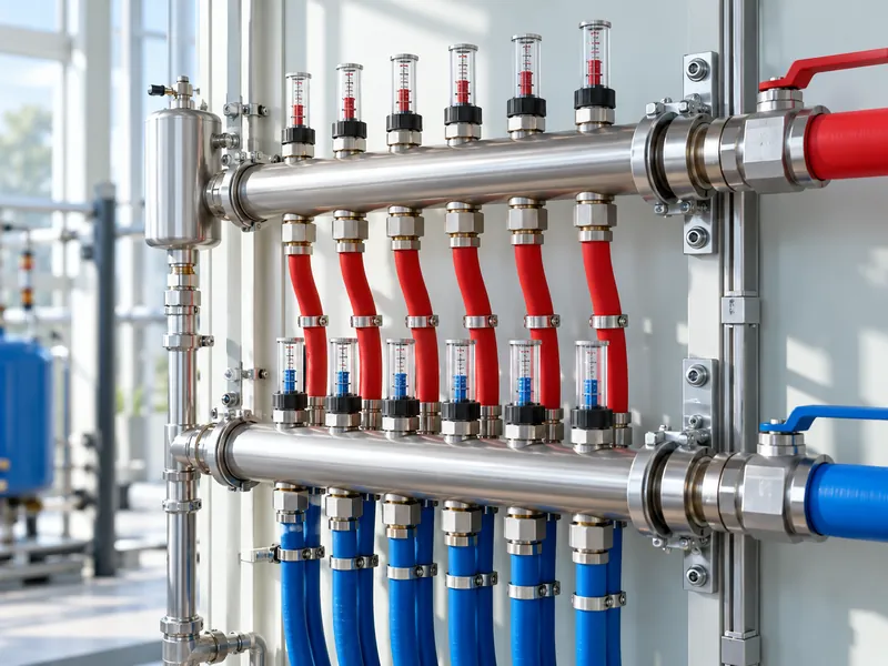
Keep pressure and flow separate in the specification. A pump may show pressure while a blocked branch receives too little water. Ask how branch performance will be measured and balanced, especially where several mold circuits share one manifold.
State the allowable pressure drop through hoses, filters, connectors, and the machine. Include the return path and any elevation effects in the system design. The pump must serve the complete installed circuit rather than only the short connection shown in a catalog drawing.
How Is the Cooling Load Estimated?
The equipment supplier should provide the thermal duty for the proposed process and explain its operating assumptions. The cooling-system designer then selects equipment for the required leaving-fluid temperature and site conditions. Ask the chiller vendor to recalculate available cooling at your specified fluid temperature and the hottest expected installation conditions before accepting the catalog rating.
For water, a useful heat-balance relationship is heat transfer in kilowatts approximately equal to 1.163 multiplied by flow in cubic meters per hour and the temperature rise in degrees Celsius. For illustration, 2 cubic meters per hour warming by 3 degrees corresponds to about 7 kilowatts of heat transfer. This calculation does not independently establish the chiller size or the required mold flow.
Use the correct fluid properties if the system contains glycol or another approved mixture. The designer must also account for pump heat, other connected loads, controls, and the selected operating reserve. Avoid adding multiple unexplained safety factors that lead to oversized equipment with poor control at normal load.
How Should the Circuits Be Arranged?
Follow the tooling and machine suppliers’ circuit design rather than connecting all available ports indiscriminately. Separate circuits may be needed for mold bodies, bases, or other components with different requirements. Label supply and return connections so maintenance does not unintentionally reverse or bypass a branch.
Choose hoses and connectors for the specified pressure, temperature, fluid, and movement. Route them to avoid kinks, abrasion, and interference with mold opening or service access. Quick connections should be checked for restrictions and secure engagement after each tooling change.
Provide accessible measurement and isolation points. A technician should be able to identify a low-flow branch without dismantling unrelated equipment. Include a procedure for restoring the approved valve positions after maintenance or balancing work.
How Do You Protect the Preform Neck?
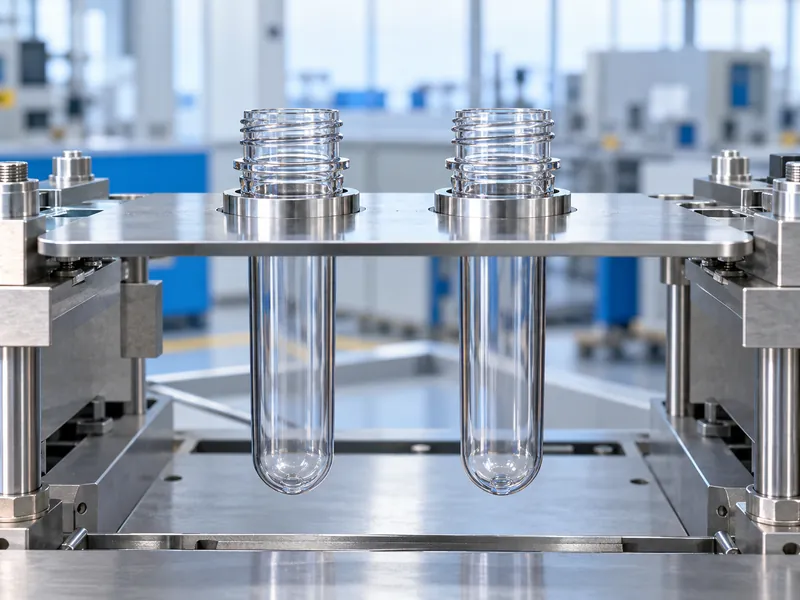
Confirm that shields, supports, and ventilation match the neck finish and preform geometry. Their position relative to the heated body matters because the neck must remain dimensionally stable while the body reaches its forming condition. Inspect for damaged shields, incorrect settings, and blocked ventilation before compensating with a new oven recipe.
Define the neck dimensions and functional checks that will be measured during acceptance. Include roundness, sealing surface, thread condition, and support-ring behavior as required by the package drawing. Test after representative production time because heat accumulation may not appear in the first few bottles.
Changing the preform or neck finish should trigger a compatibility review. A support arrangement that works for one finish may expose another to excess heat or mechanical loading. Store the approved setup with the format recipe and tooling record so it can be repeated.
Can Colder Water Create Problems?
Lowering the setpoint is not a universal cure for a cooling complaint. Moisture from the room air can collect as droplets on sufficiently cold tooling or pipework, so the designer must consider the local humidity as well as the water temperature. That can complicate cleanliness, create dripping, and obscure the real cause of a process instability.
Investigate inadequate flow, fouling, incorrect connections, and heat load before lowering temperatures outside the approved range. Discuss insulation and humidity management with the system designer where condensation is expected. The operating target should meet the process requirement with stable control.
Check water quality and the compatibility of every wetted material. Scale, corrosion products, or biological deposits can reduce performance over time. Use the supplier-approved treatment and cleaning program rather than an improvised chemical mix that may damage seals or tooling.
What Should Be Verified During Commissioning?
Measure supply and return temperatures, branch flow, and pressure conditions during sustained production. Confirm that every cavity meets bottle quality requirements at the agreed rate. Include the simultaneous utility loads that the installation is expected to support.
Demonstrate the response to a cooling fault using the manufacturer’s approved test method. Operators need a clear indication and a defined response when flow or temperature becomes unacceptable. Record which conditions stop production and how affected bottles are identified after a fault.
Repeat relevant checks after a representative mold change and restart. This reveals connection mistakes and recovery behavior that a single stable run may miss. Keep the commissioning measurements as the baseline for later maintenance comparisons.
How Should Cooling Performance Be Managed Over Time?
Trend the measured conditions alongside bottle quality, cycle time, and maintenance events. A rising temperature difference or falling branch flow can justify investigation, but interpret it with the actual production load. Compare equivalent formats and operating states before concluding that equipment has deteriorated.
Include cooling energy, water treatment, cleaning, and maintenance in the bottling line operating-cost assessment. Keep responsibility for the cooling installation in the production maintenance plan after commissioning, with a named owner for its settings, service records, and future capacity reviews. Maintain a clear circuit drawing and approved settings so reliable cooling survives staffing changes and future expansion.