
Size a PET blowing air system from the machine’s verified air demand at the required bottle output and pressure, then account for treatment losses, pressure drop, transient demand, site conditions, and operating reserve. Confirm whether each quoted flow is free air delivery, normal flow, or actual compressed volume. Selecting a compressor by motor power or bottle volume alone can leave the blower short of usable air.
What Information Must Come From the Blower Supplier?
Request an air-consumption schedule for every important bottle format and production recipe. The schedule should identify the required inlet pressure range, average consumption, peak demand, permitted pressure fluctuation, and air-quality specification. It should also state whether an air-recovery option is included in the quoted consumption.
Different services may operate at different pressures. Blowing air, pre-blowing air, and pneumatic actuators do not necessarily share one supply arrangement. Ask for a connection diagram showing which loads belong to the high-pressure system and which are supplied separately.
- Bottle size, preform, mold, cavity count, and guaranteed production rate.
- Air consumption with clearly stated reference temperature and pressure.
- Minimum dynamic pressure measured at the machine inlet.
- Peak flow or cycle-demand information needed for receiver sizing.
- Dryness, particle, oil, and any application-specific air-quality requirements.
- Recovery-system performance and the operating conditions behind it.
Use the selected PET bottle blowing machine specification as the starting point. A utility package developed for a different model or bottle can be misleading even when the nominal output looks similar. Keep the air schedule attached to the purchase specification.
Why Must Flow Units Be Reconciled?
A cubic meter of air at high pressure does not contain the same mass as a cubic meter at atmospheric pressure. Compressor delivery and blower consumption can therefore look very different when they use different reference conditions. Convert both to an agreed basis before adding demands or comparing quotations.
Free air delivery refers to delivery expressed at specified inlet reference conditions, while normal-volume figures use a defined reference state. The word “normal” is incomplete unless its temperature and pressure basis are stated. Ask the supplier to clarify ambiguous units instead of assuming every value labeled cubic meters per minute is directly comparable.
How Can You Make a Preliminary Demand Calculation?
If consumption is provided as normal liters per bottle, multiply by bottles per hour and divide by 1,000 to obtain normal cubic meters per hour. This is a planning calculation for the same bottle, rate, pressure, and recovery arrangement used in the supplier’s figure. Treat this calculated flow as a starting demand estimate; the compressor supplier must still account for operating pressure, site conditions, control behavior, and treatment losses before selecting equipment.
For illustration, assume 18 normal liters per bottle at 6,000 bottles per hour. The blowing demand is 108 normal cubic meters per hour on that stated basis. If treatment and other identified loads require another 12 normal cubic meters per hour, the preliminary continuous total becomes 120 before the agreed reserve and site corrections.
Those values are hypothetical, not standard PET consumption figures. A calculation based only on bottle volume multiplied by pressure can overlook dead volume, pre-blowing, air recovery, leakage, and valve behavior. Use it only as an engineering cross-check when its assumptions are understood.

How Do You Choose the Required Pressure?
Begin with the minimum pressure needed at the blower inlet while the machine is consuming air. Work upstream through the dryer, filters, valves, and piping to estimate the compressor discharge requirement. Static pressure observed while production is stopped cannot confirm that sufficient pressure is available during a blowing cycle.
Check the supplier’s permitted pressure range rather than maximizing the setting. Unnecessary compression increases energy use and can conceal a restrictive pipe or filter. If the inlet pressure falls during demand peaks, first establish whether the cause is inadequate delivery, insufficient storage, or excessive distribution loss.
How Should Receivers and Piping Be Sized?
A receiver provides short-term storage between compressor delivery and fluctuating demand. To specify usable storage, give the system designer the lowest acceptable machine-inlet pressure together with a time-based record of the short demand peaks that the compressor cannot immediately supply. A large receiver cannot permanently compensate for a compressor that delivers less air than the average requirement.
Ask the air-system designer to size storage using the blower’s cycle profile, compressor controls, and allowable pressure dip. Include the actual receiver location because storage separated from the blower by restrictive piping may not respond as intended. Vessel ratings and installation requirements must be handled by qualified suppliers.
Size the distribution system for the required flow at its operating pressure and acceptable pressure loss. Include fittings, flexible connections, isolation valves, and treatment equipment in the assessment. A short undersized hose at the machine can become the limiting section even when the main header is generous.
What Air-Treatment Loads Must Be Included?
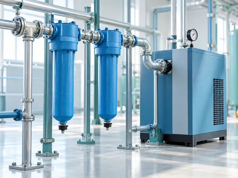
Include any air consumed by the selected dryer and the pressure loss across the treatment train. Dryer technologies differ, and their capacity depends on operating conditions. Confirm the rated inlet temperature, ambient temperature, pressure, and flow before accepting a catalog capacity.
| System Element | Information to Confirm | Reason It Matters |
| Compressor | Delivered flow at required discharge pressure and site conditions | Motor rating alone does not establish available air |
| Dryer | Corrected flow capacity, pressure dew point, and purge demand | Moisture control and usable delivery depend on the selected design |
| Filters | Required air quality and clean-to-service pressure loss | Contamination control must remain effective without excessive restriction |
| Receiver | Usable storage over the permitted pressure range | Supports transient demand without masking average undersizing |
| Distribution | Flow capacity and total pressure loss to the machine | Pressure at the compressor is not pressure at the blower |
Specify compressed-air quality at the point where the air is used. An oil-free compressor does not by itself resolve contamination introduced through intake air, piping, receivers, or downstream components. The treatment and verification plan should reflect the bottle’s intended application.
How Much Reserve Should You Add?
Set reserve from identified uncertainties and the plant’s continuity requirements rather than applying an unexplained percentage. Consider measured leaks, expected expansion, simultaneous users, and maintenance availability. Excessive oversizing can also be inefficient when the compressor spends much of its time poorly loaded.
Separate capacity reserve from redundancy. Spare flow available during normal operation does not mean the plant can continue if its only compressor is unavailable. Where a stoppage would interrupt the whole bottling line, evaluate an appropriate backup arrangement and the controls needed to use it.
Compare alternatives at realistic demand profiles, including reduced-speed production and standby. The broader bottling line cost assessment should include compressor energy and service alongside blower ownership costs. A lower initial compressor price may be offset by a poor operating match.
Which Site Conditions Can Change the Result?
Provide the compressor supplier with altitude, ambient temperature range, ventilation conditions, and cooling arrangements. These influence equipment performance and may require rating corrections. Locate the intake and equipment so that the installation meets the supplier’s environmental requirements.
Account for heat rejection and maintenance clearance in the layout. A utility room that becomes hotter during a long production run may behave differently from the conditions observed during commissioning. Record inlet and ambient temperatures during acceptance testing.
How Do You Verify the Installed System?
Test the air system while the blower produces the intended bottles at the agreed rate. Measure pressure near the machine inlet and log enough detail to reveal cyclic dips and sustained losses. Record compressor loading, air flow, treatment performance, and electricity over the same interval.
- Confirm the installed equipment and pipe arrangement against the approved design.
- Check pressure and flow instrument locations and calibration.
- Run the highest-demand approved bottle recipe under representative conditions.
- Observe startup, normal cycling, and recovery after a production stop.
- Verify air-quality results using the agreed sampling method.
- Document pressure losses and accepted bottle output together.
Keep a baseline after commissioning so that rising pressure drop or consumption can be investigated later. Changes in filters, leaks, valves, recipes, or recovery performance may alter demand without any change to the nominal bottle rate. A useful specification therefore includes both the original sizing calculation and a repeatable verification method.