
A complete mineral water plant is more than a water treatment system connected to a filling machine. It is an integrated production line that receives raw water, controls its quality, prepares bottles, rinses and fills them, applies caps and labels, packs finished products, and verifies that every bottle meets the required standard.
The equipment configuration depends mainly on the raw-water condition, bottle size, production capacity, packaging method, operating hours, and automation level. Although small and large plants follow a similar process, their equipment sizes and control requirements can be very different.
The most important planning principle is production balance. The water treatment system, bottle blowing machine, three-in-one filling machine, labeler, packer, and conveyors must support the same practical capacity. One undersized section can restrict the output of the entire plant.
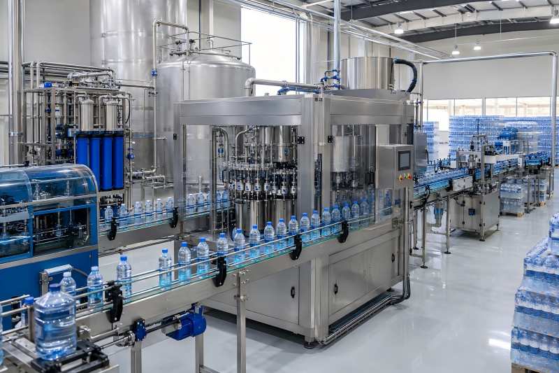
Main Production Process
A typical mineral water plant follows this process:
Raw-water collection → pretreatment → fine filtration → sterilization → treated-water storage → bottle preparation → rinsing, filling and capping → inspection → labeling → coding → packing → palletizing.
| Production Section | Main Equipment | Main Function |
| Raw-water supply | Source pump and storage tank | Provides a stable water supply |
| Pretreatment | Sand filter, carbon filter and optional softener | Removes particles, odor, chlorine and scale risks |
| Fine treatment | Cartridge filter, UF, NF or RO system | Controls fine contaminants |
| Sterilization | UV sterilizer and ozone system | Reduces microbial risks |
| Water storage | Treated-water tank and sanitary pipes | Supplies clean water to the filler |
| Bottle preparation | Blow molding machine and air system | Produces PET bottles |
| Filling | Three-in-one monoblock machine | Rinses, fills and caps bottles |
| Packaging | Labeler, coder and packing machine | Produces finished retail packs |
| Cleaning and testing | CIP system and laboratory equipment | Maintains hygiene and quality |
1. Raw-Water Pump and Storage Tank
The production process starts at the water source. Mineral water may come from an underground well, protected spring, borehole, or another approved source.
The first equipment normally includes a source pump, raw-water tank, flow meter, valves, level sensors, and pressure-control system.
The source pump should provide stable flow and pressure. Excessive pressure fluctuations may disturb filtration performance and increase wear on downstream equipment. A variable-frequency drive allows the pump to adjust its speed according to actual water demand.
The raw-water tank works as a production buffer. It prevents temporary changes in the source supply from immediately affecting the treatment system.
A practical tank usually stores approximately one to two hours of treatment capacity. For example, a treatment system rated at 10,000 liters per hour may use a raw-water tank with a capacity of around 10,000 to 20,000 liters.
A larger tank is not always better. It occupies more factory space, requires more cleaning, and may increase the time that untreated water remains in storage.
2. Water Pretreatment Equipment
Pretreatment protects fine filters and membrane systems while improving water-quality stability. The exact equipment should be selected according to a detailed raw-water analysis.
Important factors include turbidity, hardness, iron, manganese, chlorine, dissolved solids, odor, microorganisms, and organic matter.
Sand or Multi-Media Filter
A sand or multi-media filter removes rust, silt, sediment, and suspended particles.
The filter may contain several layers of media with different particle sizes. Larger impurities are captured near the top, while smaller particles are trapped deeper inside the filter bed.
Automatic control valves can manage filtration, backwashing, and rinsing. Larger plants may install two parallel filters so production can continue while one filter is being cleaned.
Activated Carbon Filter
Activated carbon reduces undesirable odor, organic compounds, and residual chlorine.
Removing chlorine is particularly important when sensitive membrane equipment is installed after the carbon filter. Excessive chlorine may damage some membrane materials.
However, the carbon bed must be cleaned and sanitized regularly. Without proper maintenance, it may become a location for microbial growth.
Softener or Scale-Control System
A softener may be required when the raw water contains high levels of calcium and magnesium. These minerals can form scale inside membranes, valves, tanks, and pipelines.
A mineral water plant should not automatically remove all hardness. Natural minerals may be an important part of the final product.
The treatment design should control scale while preserving the intended mineral composition whenever the source condition and product requirements allow it.
3. Fine Filtration and Membrane Equipment
After pretreatment, the water normally passes through one or more fine-treatment stages. These may include cartridge filtration, ultrafiltration, nanofiltration, or reverse osmosis.
Cartridge Filters
Cartridge filters capture smaller particles that pass through the media filters.
A plant may use a 5-micron filter followed by a 1-micron filter. Pressure gauges installed before and after the filter housing help operators determine when the cartridges need replacement.
Cartridge filtration is relatively simple and inexpensive, but replacement frequency depends heavily on the incoming water quality.
Ultrafiltration System
Ultrafiltration removes fine particles, colloids, and many microorganisms while allowing most dissolved minerals to remain in the water.
This makes it useful when the raw water already has a suitable mineral composition but requires stronger clarification and microbial control.
An ultrafiltration system should include automatic flushing and chemical-cleaning connections. Without regular cleaning, membrane flow may decrease over time.
Reverse Osmosis System
Reverse osmosis provides stronger control over dissolved salts, hardness, and unwanted substances.
It may be necessary when raw water has unstable mineral levels, excessive dissolved solids, or contaminants that cannot be adequately controlled by conventional filtration.
However, reverse osmosis also removes much of the natural mineral content. It should therefore not be treated as a mandatory component of every mineral water plant.
Some plants use partial RO treatment, blending, or controlled remineralization to achieve consistent water quality while maintaining the required mineral profile.
| Treatment Method | Mineral Retention | Approximate Water Recovery | Main Purpose |
| Cartridge filtration | Very high | Above 98% | Fine particle removal |
| Ultrafiltration | High | 90–97% | Colloid and microbial control |
| Nanofiltration | Medium | 75–90% | Partial salt and hardness reduction |
| Reverse osmosis | Low without blending | 60–85% | Strong dissolved-solid control |
These values are planning ranges rather than guaranteed figures. Actual recovery depends on raw-water chemistry, temperature, membrane selection, pressure, and system design.
4. UV Sterilizer and Ozone System
UV sterilization and ozone treatment are often used together because they provide different types of microbial protection.
A UV sterilizer exposes flowing water to ultraviolet light. It works quickly and does not add chemicals to the product.
Its performance depends on water clarity, lamp intensity, flow rate, and the cleanliness of the protective sleeve. UV mainly treats water at the point of exposure and does not provide long-term residual protection.
Ozone can be mixed with treated water to provide temporary protection inside the treated-water tank and filling circuit.
A complete ozone system may include:
- Ozone generator
- Oxygen source or air preparation unit
- Ozone injector
- Mixing device
- Contact tank
- Ozone concentration monitor
- Off-gas treatment device
Ozone concentration must be controlled carefully. Insufficient ozone may provide inadequate protection, while excessive ozone may affect taste, packaging materials, equipment seals, and workplace safety.
5. Treated-Water Tank and Sanitary Piping
After treatment, the water is stored temporarily before filling. The treated-water tank is normally manufactured from stainless steel and uses a closed sanitary design.
The tank should include level sensors, a sanitary vent filter, spray-cleaning device, sampling valve, drainable bottom, and protected access opening.
Product-contact pipelines should have smooth internal surfaces and as few dead ends as possible. Water remaining in unused pipe branches may become a hygiene risk.
The tank should not be unnecessarily large. A capacity equal to approximately one to two hours of filling demand usually provides a practical operating buffer.
A circulation loop can keep treated water moving when the filling machine stops temporarily. This reduces stagnation and helps maintain stable water conditions.
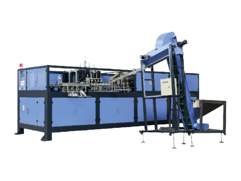
6. PET Bottle Blowing Equipment
A mineral water plant can purchase finished empty bottles or produce them internally from PET preforms.
Buying finished bottles reduces the initial equipment investment, but empty bottles occupy considerable transport and storage space. Producing bottles internally gives the plant greater control over bottle weight, shape, appearance, and supply.
A complete bottle blowing system may include:
- Preform hopper and feeder
- Preform heating oven
- PET blow molding machine
- High-pressure air compressor
- Low-pressure air compressor
- Air dryer and filters
- Compressed-air receiver
- Industrial chiller
- Bottle air conveyor
The blowing machine should normally have slightly more capacity than the three-in-one filling machine. A capacity margin of approximately 5–15% helps compensate for rejected bottles, preform differences, and short machine stops.
For a filling line rated at 12,000 bottles per hour, the blowing system may be selected for approximately 13,000 to 14,000 bottles per hour.
High-pressure compressed air is one of the largest energy consumers in PET bottle production. Correct compressor sizing, stable cooling, dry air, and regular leak inspection can significantly reduce operating costs.
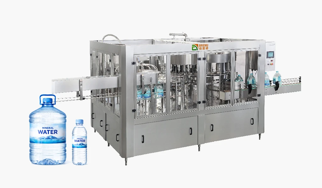
7. Three-in-One Rinsing, Filling and Capping Machine
The central production machine is the three-in-one monoblock filling machine.
It combines three operations on one integrated frame:
- Bottle rinsing
- Mineral water filling
- Cap application
Compared with three separate machines, the monoblock design reduces bottle transfers, saves factory space, simplifies control, and lowers the risk of contamination.
Bottle Rinsing Section
Empty bottles enter the three-in-one machine through an air conveyor.
The rinser grips each bottle by the neck, turns it upside down, and sprays the internal surface with treated water or another approved rinsing medium.
After rinsing, the bottle drains before being transferred directly to the filling section.
Neck handling is suitable for lightweight PET bottles because the machine does not need to apply pressure to the bottle body.
Mineral Water Filling Section
Still mineral water is generally filled by gravity or controlled low pressure.
Water enters the bottle through a filling valve until the required liquid level is reached. The valve then closes, and the bottle moves toward the capping section.
Filling-valve design directly affects production speed, liquid-level accuracy, dripping, and cleaning efficiency.
The machine should also maintain stable water conditions inside the filling tank. Automatic level control helps keep the filling pressure consistent across all valves.
The product-contact components should have smooth surfaces and be accessible to the CIP system. Poorly designed corners or undrainable areas can create sanitation problems.
Bottle Capping Section
After filling, bottles immediately enter the capping turret.
Caps are loaded into a cap hopper and transported through an elevator. A sorter places every cap in the correct direction before it enters the cap chute.
The capping heads apply controlled torque. Insufficient torque can cause leakage, while excessive torque may damage the threads, cap, or bottle neck.
Sensors can identify missing caps, incorrectly positioned caps, and bottles that fail to enter the capping station correctly.
| Output for 500 mL Bottles | Example Configuration | Product Output | Suitable Plant Size |
| 2,000 BPH | 8-8-3 | 1,000 L/h | Small local plant |
| 6,000 BPH | 18-18-6 | 3,000 L/h | Regional supplier |
| 12,000 BPH | 24-24-8 | 6,000 L/h | Medium commercial plant |
| 24,000 BPH | 40-40-10 or larger | 12,000 L/h | Large-volume plant |
The three configuration numbers generally represent rinsing stations, filling valves, and capping heads. Actual configurations vary according to bottle size and machine design.
The rated output should not be confused with average daily production. Cleaning, cap replenishment, bottle changes, rejected materials, and short stops all reduce practical output.
8. Bottle Conveyors and Cap Feeding Equipment
Air conveyors are generally used for empty PET bottles because they support the bottles by the neck. Filled bottles are normally moved on motor-driven chain conveyors.
A well-designed conveyor system prevents bottle falls, scratches, excessive pressure, and unstable transfers between machines.
Accumulation sections should be installed between major production stages. A buffer of several minutes allows the filling machine to continue operating during a short downstream interruption.
The cap-feeding system normally includes a cap hopper, elevator, sorter, chute, and detection sensors. Cap-contact surfaces should be easy to clean because the cap directly seals the bottle opening.
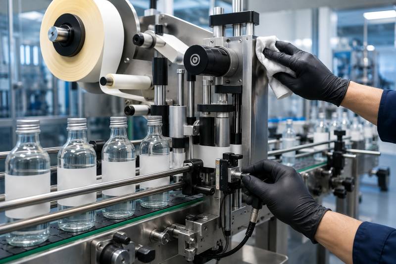
9. Labeling and Coding Equipment
The labeling machine should match the bottle shape, production speed, and selected label material.
Shrink-sleeve labelers are suitable for shaped bottles and labels covering a large surface area. OPP hot-melt labelers are commonly used for high-speed cylindrical bottles.
Self-adhesive labelers offer greater flexibility for lower production volumes, transparent labels, or premium product designs.
A coding machine prints information such as:
- Production date
- Expiry date
- Batch number
- Production line number
- Traceability code
Inkjet coding is flexible and works with many packaging materials. Laser coding reduces ink consumption but requires suitable bottle, cap, or label materials.
Inspection sensors or camera systems can verify label position and code presence. At high speeds, manual inspection alone may not identify every packaging defect.
10. Packing and Palletizing Equipment
Finished bottles must be grouped into stable packs for storage and transportation.
A shrink wrapping machine arranges bottles into a selected format, wraps them with film, and passes the pack through a heat tunnel.
Common formats include 6, 12, or 24 bottles per pack. Shrink wrapping has relatively low material costs and is widely used for standard bottled water.
Carton packing provides better product protection and more printable surface area. It may be more suitable for longer transportation distances or retail channels that require boxed products.
Large plants may also use:
- Automatic palletizer
- Pallet dispenser
- Stretch wrapping machine
- Finished-pallet conveyor
- Warehouse transfer system
Smaller plants may use manual palletizing, but labor cost, lifting frequency, and worker safety should be considered.
11. CIP Cleaning System
A clean-in-place system circulates cleaning liquids through tanks, pipelines, and filling-machine product paths without completely dismantling the equipment.
A typical CIP station may include:
- Hot-water tank
- Alkaline solution tank
- Optional acid solution tank
- Circulation pump
- Heat exchanger
- Chemical dosing system
- Conductivity and temperature instruments
Mineral water plants mainly need to control mineral scale, microbial buildup, and residue inside sanitary pipelines.
The cleaning process should not simply copy a juice or carbonated-drink CIP program. Mineral water contains no sugar or fruit material, so its cleaning requirements are different.
Temperature, flow rate, cleaning time, and solution concentration should be monitored. Automated CIP improves consistency, but the final results should still be verified through inspection and microbial testing.
12. Laboratory and Quality-Control Equipment
A mineral water plant needs basic laboratory equipment even when its treatment and filling systems are highly automated.
Common instruments include:
- pH meter
- Conductivity meter
- Turbidity meter
- Total dissolved solids meter
- Ozone test instrument
- Microbiological incubator
- Membrane filtration unit
- Bottle torque tester
- Precision weighing scale
The plant should inspect both the water and its packaging.
Water checks may cover clarity, odor, taste, conductivity, mineral composition, and microorganisms. Packaging checks may include bottle weight, fill volume, cap torque, leakage, label position, and pack strength.
13. Utility and Supporting Equipment
Several support systems are necessary for reliable production but are sometimes missing from initial equipment plans.
These include:
- High-pressure compressed air for bottle blowing
- Low-pressure air for pneumatic valves and cylinders
- Industrial water chiller
- Electrical control cabinets
- Voltage stabilizing and protection devices
- Drainage and wastewater collection
- Workshop ventilation
- Maintenance tools
- Spare-parts storage
- Backup power for critical controls
The workshop should separate water treatment, bottle blowing, filling, packaging, laboratory, and material-storage areas. Proper zoning helps reduce unnecessary movement between clean and less-clean sections.
Example Equipment Balance for a 12,000-BPH Plant
The following example assumes 500 mL bottles and an average operating efficiency of approximately 85%.
| Equipment | Recommended Capacity | Selection Reason |
| Water treatment system | 8,000 L/h | Covers product water, rinsing and normal losses |
| Treated-water tank | 10,000–15,000 L | Provides a practical filling buffer |
| Bottle blowing machine | 13,000–14,000 BPH | Maintains capacity above the filler |
| Three-in-one filling machine | 12,000 BPH | Defines the main line output |
| Labeling machine | 13,000–15,000 BPH | Prevents labeling bottlenecks |
| Shrink wrapper | 12–15 packs/min | Depends on bottles per pack |
| Conveyor accumulation | 3–8 minutes | Absorbs brief production stops |
At 12,000 bottles per hour, 500 mL bottles contain 6,000 liters of finished water.
A treatment system rated at exactly 6,000 liters per hour would provide almost no additional capacity for bottle rinsing, cleaning, rejected product, or flow fluctuations. An 8,000-liter-per-hour treatment system therefore provides a more realistic margin.
The labeler and bottle blowing machine are also selected above the filling speed. This prevents small performance changes in these sections from repeatedly stopping the three-in-one filling machine.