
Before connecting a monoblock filler to an existing CIP system, verify the complete cleaning circuit, supply and return capacity, chemical and temperature compatibility, control handshake, drainage, and acceptance method. Confirm that the plant skid can deliver the required conditions through the actual installed route. Matching pipe connections or having spare pump capacity does not prove that the filler can be cleaned effectively.
Start with a joint review by the filler supplier, CIP supplier, plant engineering team, and quality team. The connection crosses equipment boundaries, so responsibility must be assigned for both the hardware and the cleaning sequence. Keep unresolved assumptions visible until they are tested.
Which Filler Components Will the CIP Route Reach?
Compare the current plant CIP diagram with the filler supplier’s circuit drawing. Mark the proposed supply, each wetted assembly intended for cleaning, and the point where solution returns to the plant. Identify bypasses and side branches explicitly, and list components that require another cleaning route or manual treatment.
Confirm which filling valves, tanks, manifolds, and return passages are covered. Review how cleaning cups or other return arrangements engage, where fitted. The rinser and capper may have separate cleaning requirements that are not part of the product CIP loop.
When selecting a monoblock filling machine, ask for an explicit cleaning boundary. List manual cleaning, removal, inspection, or external washdown tasks separately so they are not lost behind a broad “CIP-ready” description.
Can the Existing Skid Supply the Required Conditions?
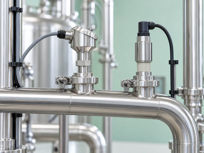
Compare the filler requirements with the conditions available at its connection while the planned plant operating scenario is in effect. Review flow, pressure, temperature, solution volume, and the intended cleaning sequence. Include any other circuit that may operate at the same time.
Calculate or otherwise verify the installed hydraulic duty with the actual pipe lengths, elevations, fittings, valves, and equipment resistance. A pump’s nameplate capacity is not the delivered flow through the completed loop. Confirm both normal operation and the limiting circuit configuration.
Check tank capacity for the total loop inventory, return behavior, and the required operating reserve. Review heating capacity and the time needed to establish the approved conditions. Extending pipework can change both the liquid volume and the heat loss from the original CIP installation.
What Must Be Checked on the Return Side?
Verify that the return arrangement can remove the cleaning liquid at the required rate without causing unacceptable retention or pressure. Include elevation changes and any air-handling requirement identified by the supplier. Supply flow and return capability must be assessed together.
Ask how the filler drains at the end of each stage and whether liquid can remain in low points or closed branches. Show the return and drain valve positions in the sequence. A visually convenient hose route can create a retained pocket if its geometry is not controlled.
Confirm where each phase returns: recovery tank, rinse-water tank, or drain, as applicable. The routing logic must suit the plant’s chemical recovery and contamination-control strategy. Avoid assuming that the existing return program recognizes a newly added machine automatically.
| Interface | Required Check | Evidence to Retain |
| Supply | Flow, pressure, temperature, available volume | Installed-duty measurements |
| Return | Capacity, drainage, destination selection | Return-path and sequence verification |
| Materials | Complete product and chemical exposure | Component compatibility schedule |
| Controls | Ready, active, fault, and complete signals | Functional handshake test |
| Cleaning result | Soil removal and rinse acceptance | Approved validation records |
Are the Materials Compatible With the Existing Recipe?
Compare every wetted material and seal compound with the plant’s cleaning chemicals, concentrations, temperatures, and exposure times. Include the maximum permitted values and any sanitizing step. Do not transfer a recipe simply because another machine on the same skid uses it.
Review hoses, valve seats, instrument surfaces, cleaning cups, and temporary connections as well as the main stainless piping. A single incompatible component can limit the circuit. Obtain a written compatibility decision for any uncertainty before commissioning.
Keep cleaning effectiveness and material limits in the same review. Reducing a temperature to protect a seal may require a revised cleaning process, while increasing concentration can affect more than cleaning speed. Changes need an agreed technical assessment rather than an isolated adjustment at the skid.
Where Should Cleaning Conditions Be Measured?
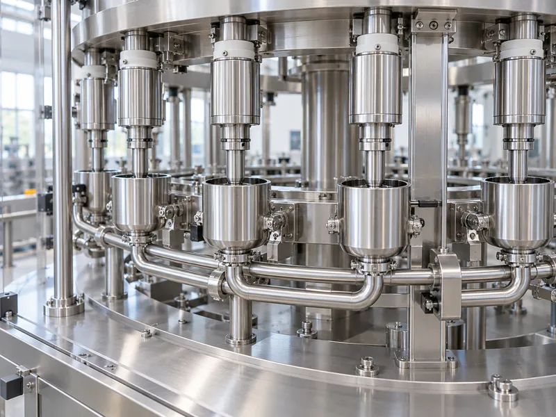
Identify the measurements that demonstrate the required conditions at the relevant part of the circuit. Supply temperature alone may not represent a distant return point during warmup. Agree where temperature, flow, pressure, and chemical-strength indicators are needed and how their records will be used.
Conductivity can support cleaning-agent monitoring and phase separation when configured for the actual medium and temperature. Alfa Laval describes temperature compensation and application-specific conductivity measurement for CIP duties. A conductivity value should not be treated as a universal concentration measurement for every chemical mixture.
Define calibration requirements, alarm limits, and the response to an unavailable or implausible signal. State when the qualifying hold time begins and what happens if a required condition is lost. A timer running while the process remains outside its approved limits cannot establish the intended exposure.
How Should the Two Control Systems Communicate?
Prepare an interface list showing which controller owns each action and which signals permit the next step. Typical functions include circuit request, machine ready, route confirmed, cleaning active, fault, stage complete, and release to production. Use names that are meaningful to both suppliers.
Confirm how the filler establishes the cleaning configuration before solution is admitted. Include the required position feedback for valves and return devices where provided. The skid must not rely on an assumed mechanical state that the filler has not confirmed.
- Define the start authorization and selected circuit identity.
- Verify the permitted supply and return routes.
- Specify responses to lost communication and utility failure.
- Record aborted cycles distinctly from completed cycles.
- Prevent production release until the required completion conditions are met.
Test the handshake with both controllers connected. A successful simulated input at one panel does not verify the complete interface. Record any simulation used and the physical behavior that still needs site testing.
How Are Product and Cleaning Solution Kept Separate?
Review the isolation arrangements between the cleaning circuit, product supply, and any neighboring equipment. The required valve configuration and monitoring depend on the process design. Confirm the intended response to leakage or an incorrect route through the approved engineering review.
Identify manual connections that could be interchanged and provide the plant’s agreed identification or connection-control method. Keep the operating procedure consistent with the physical arrangement. A correct diagram is insufficient if the normal hose setup can connect the wrong destination.
Define the final rinse endpoint and the evidence required before product admission. The appropriate check depends on the chemical and product; do not rely on appearance alone. Document how the first product after cleaning is handled and released.
What Records Should Each Cycle Produce?
Record circuit identity, recipe revision, start and finish times, stage transitions, qualifying measurements, alarms, and completion status. Retain interruptions and operator interventions. These details allow the quality team to distinguish a completed approved cycle from one that merely ran for the expected duration.
Agree how records move between the filler, skid, and plant archive. Synchronize timestamps sufficiently to reconstruct the sequence and identify missing data. Confirm retention and retrieval during the acceptance test rather than waiting for the first investigation.
How Should the Installed Connection Be Accepted?
Begin with a controlled functional test of routing, drainage, interlocks, and recovery actions using the approved commissioning procedure. Measure the delivered conditions through the real installed loop. Correct interface defects before evaluating the full cleaning result.
Then execute the agreed cleaning qualification with representative product soil and suitable inspection or analytical methods. Choose sampling locations and acceptance criteria with the quality team, including difficult-to-clean areas. Meeting flow and temperature targets supports the assessment but does not replace evidence of the cleaning outcome.
Finish with an updated diagram, approved recipe, interface record, maintenance instructions, and a list of any remaining manual tasks. Train the operating team on aborted-cycle recovery and release conditions. Reassess the connection when products, chemicals, piping, or concurrent CIP demand change.
For an interface review, provide Brenu with the existing CIP diagram and operating recipe. Request a documented supply, return, controls, and validation scope so the new filler can be integrated into the plant’s cleaning process with clear responsibilities.