
A monoblock filler may need new bottle infeed screws, starwheels, guide rails, rinser grippers, filling supports, and cap-handling components when the package changes. The actual list depends on bottle geometry, neck finish, closure design, and the machine’s handling method. Require a format-by-format parts matrix with drawings and an operating trial before treating two bottles as interchangeable.
A small bottle-volume difference can require several mechanical changes, while a large volume difference may need only height adjustment on a neck-handling design. Start with the package dimensions that touch the machine. Nominal capacity alone cannot identify a compatible set of parts.
Which Bottle Information Should You Supply?
Provide controlled bottle and closure drawings, physical samples, and the intended operating conditions. Include the maximum body diameter or width, height, neck finish, support-ring geometry, shoulder profile, and base shape. Identify dimensions with meaningful manufacturing variation rather than sending a single attractive sample.
Describe the container condition at each transfer, including whether it is empty, wet, filled, or pressurized. Flexible walls can respond differently as the process changes the load on the package, so evaluate supports at the station where they operate. For glass, include container mass, dimensional variation, and the handling provisions appropriate to breakage.
- Give every bottle and cap combination a unique format identifier.
- Include dimensional tolerances and approved sample references.
- State the required throughput for each combination.
- Identify orientation requirements for shaped bottles.
- Record label or sleeve features that may contact downstream guides.
Use this package schedule when discussing the monoblock filling machine configuration. Ask the supplier to identify both the parts that change and the components retained across formats. A quotation saying only “additional bottle size” leaves too much undefined.
Where Do Bottle Change Parts Usually Appear?
Does the Infeed Need a Different Screw or Guide?
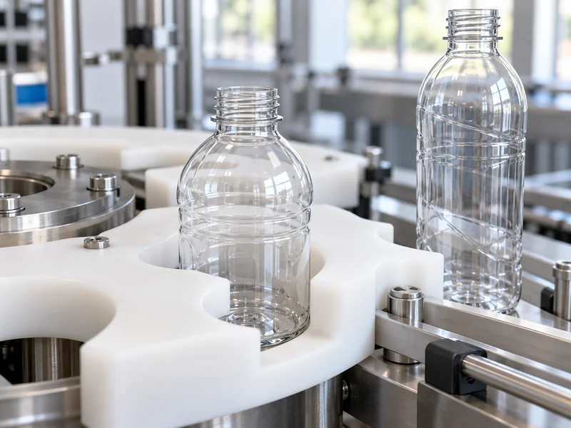
A timing screw, where fitted, spaces bottles into the machine’s pitch. Its profile must suit the relevant bottle section and transfer arrangement. A different body diameter, asymmetric shape, or unstable base can alter how the bottle enters the first starwheel.
Check infeed side guides, bottle supports, and transitions at the conveyor interface. Some are adjustable, while others use dedicated inserts or rails. Record setting references so the operator can restore the position without repeated trial runs.
Which Starwheels and Guides Must Change?
Body-handling starwheels generally need pockets that fit the bottle profile and coordinate with the surrounding guide. A shared wheel may cover a defined group of formats, but that range must be demonstrated. Too much clearance can allow movement; an unsuitable pocket can pinch or mark the container.
Map every transfer point, including entry to the rinser, transfer into filling, movement into capping, and discharge. Do not count only the visible large starwheel. Small guides and transfer inserts can determine whether a changeover succeeds.
Can Neck Handling Reduce the Parts List?
On an appropriate neck-handling machine, bottles with a common neck and support-ring specification may share more handling components. Krones describes neck-gripper arrangements on some PET filling equipment, illustrating why body volume is not the only changeover variable. That principle must still be checked against the proposed machine’s actual design.
Common neck geometry does not automatically resolve body clearance, rinsing inversion, fill height, or capper access. Ask which bottle envelope was qualified with the retained grippers. Confirm the largest shoulder and widest body at every rotational and transfer position.
What Changes at the Rinsing and Filling Stations?
Rinser clamps or grippers must hold the bottle throughout inversion and return without damaging the neck or slipping. Nozzle alignment and insertion clearance must suit the mouth and interior geometry. Some formats require a different gripper insert or support, while others use a documented adjustment.
At the filler, review bottle centering, lifting platforms, neck supports, bell seals, and any nozzle or valve extension associated with the package. These components are not present in every filling technology. Ask the supplier to distinguish genuine format parts from ordinary product-setting changes.
Changing bottle height can affect lifting travel, head clearance, and the position at which a seal is established. Changing neck finish may affect the sealing interface even when the body remains identical. Verify these relationships with the approved bottle drawing and a physical fit check.
| Machine Area | Possible Change Item | Verification Needed |
| Infeed | Timing screw and guide inserts | Stable spacing and transfer |
| Rotary transfers | Starwheels and curved guides | Pocket fit and bottle clearance |
| Rinser | Gripper pads or clamps | Secure inversion and nozzle alignment |
| Filler | Supports, centering pieces, or seals | Correct positioning throughout the cycle |
| Capper | Chucks and closure guides | Closure feed and application quality |
Which Closure Parts Need Separate Review?
A cap diameter, height, thread, or tamper-band change can affect the cap sorter, chute, pickoff, applying head, and bottle restraint. A closure with a similar appearance may need a different chuck insert or feed track. Treat the closure as a controlled component rather than an accessory to the bottle drawing.
Confirm which capper adjustments are mechanical and which belong in the recipe. The machine setting must produce an acceptable finished closure under the agreed inspection method. A successful fit on the chuck does not prove correct application to the bottle.
Where several cap families are planned, request individual compatibility decisions for each bottle-cap pairing. Avoid assuming that every approved bottle can use every approved cap. A simple pairing matrix prevents unsupported combinations from entering production planning.
What Should the Format Parts Matrix Contain?
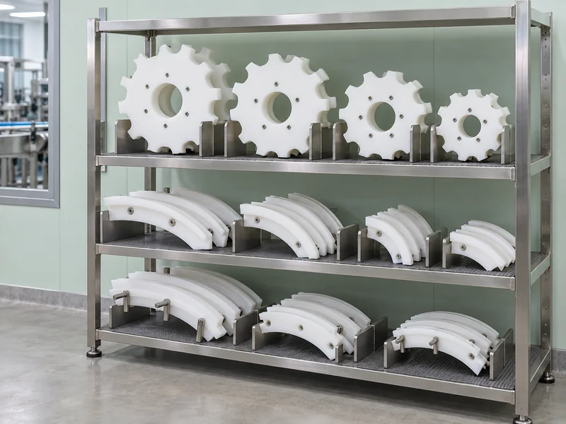
List each replaceable item by part number, description, quantity, machine location, and compatible format. Mark adjustable items separately and provide their setting references. Identify shared components clearly so purchasing does not order unnecessary duplicates.
Include the supplied quantity and the recommended spare quantity as separate columns. A single set included with the machine is different from a spare set held for damage or wear. Specify whether fasteners, spacers, and small locating pieces remain attached to the main part during removal.
Ask for durable identification that remains readable after the intended cleaning process. Color coding can help operators, but it should support a part number rather than replace one. Storage racks should protect contact surfaces and make a missing component easy to notice.
How Should You Test a Complete Format Change?
Demonstrate the change with the normal tools, instructions, and proposed operating team. Begin with one approved format running acceptably and end when the next format produces sustained acceptable bottles. Record adjustments and trial rejects alongside the mechanical swap time.
- Identify and remove the outgoing format components using the documented isolation procedure.
- Inspect locating faces and install the correct incoming set.
- Apply the recorded mechanical settings and selected recipe.
- Verify clearance with the supplier’s approved checking method.
- Run representative bottles and closures through the complete process.
- Inspect rinsing, filling, closure quality, and discharge stability.
Include the difficult formats, not only two bottles with nearly identical geometry. Check tall or light bottles, unusual shoulders, and the highest agreed speed where relevant. Record any speed restriction as part of the approved format specification.
How Do You Budget for Parts and Storage?
Compare the total format cost over the planned production mix. Include replacement components, setup labor, cleaning effort, storage, and the output lost while acceptable production is restored. A cheaper additional set may be less attractive if it requires many unmarked adjustments on every shift.
Ask which items are custom manufactured and which are standard stocked spares. Record lead times for critical polymer parts and closure tooling, especially when a damaged component would stop several formats. Keep a controlled drawing or supplier reference so a replacement matches the current machine revision.
Review the trolley and rack arrangement during the trial. Heavy or awkward components need a suitable handling method, and clean parts should not be placed on the floor while another format is removed. Count the complete set at the end of the demonstration and identify where each piece will be stored.
These practical details make the parts matrix useful on the production floor. The goal is a repeatable handover between formats with identifiable components and known settings, rather than a collection of loose wheels that only one technician understands.
How Should Future Bottle Changes Be Managed?
Reserve a review step before ordering a new bottle mold or closure. Send the proposed drawing to the machine supplier and request a written list of affected parts, settings, and performance limitations. This avoids discovering an inaccessible shoulder or incompatible neck after packaging inventory arrives.
Keep the approved matrix with the machine documentation and update it after every validated format addition. Link each recipe to the corresponding mechanical set and sample reference. Retire obsolete instructions so operators cannot accidentally combine two generations of parts.
For a new project or additional format, send Brenu the bottle and closure schedule with your required output. A useful proposal should show the complete changeover scope, supplied tooling, and evidence required to release each package combination.