
Syrup mixing connects with the filling line through much more than a product pipe. The relationship includes recipe accuracy, flow control, temperature management, carbonation, buffering, pressure stability, automation, and production scheduling.
A reliable line balances the capacity of every stage. Syrup is prepared early enough to prevent filler starvation, but not so early that finished beverage remains in storage for too long. Flow changes follow filler demand, while temperature and pressure remain stable from the carbonator to the filling valve.
The Main Production Sequence
A typical carbonated beverage process includes several connected stages:
- Water treatment
- Simple syrup preparation
- Ingredient dosing
- Final beverage blending
- Cooling and deaeration
- Carbonation
- Product buffering
- Bottle rinsing, filling, and capping
The concentrated syrup is usually not sent directly into bottles. It is first combined with treated water according to a defined ratio. The finished beverage is then cooled, carbonated, and transferred to the filling line.
| Production Stage | Main Function | Key Control Point | Possible Effect on Filling |
| Simple syrup preparation | Dissolve sugar or sweetener | Brix and temperature | Incorrect sweetness |
| Ingredient dosing | Add flavor, acid, color, and preservatives | Dosing accuracy | Batch-to-batch variation |
| Final blending | Combine syrup and treated water | Mixing ratio | Unstable product concentration |
| Cooling | Lower beverage temperature | Outlet temperature | Foaming and CO₂ loss |
| Carbonation | Dissolve CO₂ into the beverage | Pressure and CO₂ volume | Flat or over-carbonated drinks |
| Buffering | Maintain continuous supply | Tank level and pressure | Filling line interruptions |
| Filling | Dose beverage into containers | Valve pressure and fill level | Underfilling or product loss |
Each stage affects the next one. For example, a blending error cannot be corrected by adjusting the filler. The filling machine may place the correct liquid volume into every bottle while still producing a beverage with the wrong sweetness or acidity.
How the Syrup Is Prepared
Simple Syrup Mixing
The process usually begins by dissolving sugar in treated water. Heating may be used to accelerate dissolution, particularly when the formula contains a high sugar concentration.
A typical simple syrup may be prepared at 55 to 68 °Brix. The exact value depends on the product formula, available tank volume, and required dilution ratio.
The mixing system generally includes:
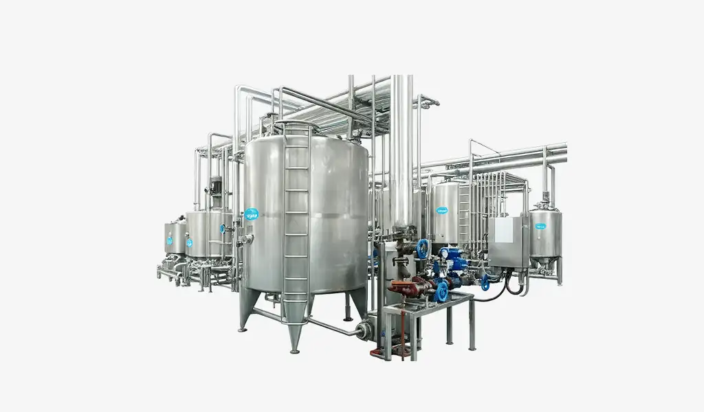
- A heated preparation tank
- An agitator
- A sugar feeding device
- Load cells or flow meters
- Filtration equipment
- A transfer pump
- Temperature and Brix measurement
The syrup must be fully dissolved before it moves to the next stage. Undissolved sugar may collect in filters, damage pump performance, or create concentration differences inside the tank.
Final Syrup Preparation
After the sugar solution reaches the required concentration, flavor concentrate, acid, color, preservatives, and other ingredients are added. Some manufacturers call this finished syrup, while others use the term concentrate.
The dosing sequence matters. Adding ingredients in the wrong order can cause poor dissolution, local concentration peaks, color instability, or unwanted reactions.
A practical sequence may be:
- Transfer the required quantity of simple syrup
- Begin controlled agitation
- Add acid solution
- Add dissolved preservatives
- Add flavor concentrate
- Add color solution
- Adjust the batch to its final weight or volume
- Mix for a defined holding time
- Test Brix, pH, appearance, and flavor
A syrup tank should not be released to production only because the ingredients have been added. Release should occur after the mixture has reached acceptable quality limits.
How Syrup Becomes the Finished Beverage
The prepared syrup is blended with treated water before carbonation and filling. This can be completed through batch blending or continuous proportioning.
Batch Blending
In batch blending, syrup and water are transferred into a finished-beverage tank. The complete batch is mixed, tested, and released before it is sent forward.
This approach is suitable for smaller plants, frequent flavor changes, and products requiring longer mixing times.
Its main limitation is the stop-start production pattern. If the finished-beverage tank becomes empty before the next batch is ready, the filler must slow down or stop.
Continuous Proportioning
A continuous proportioning system meters syrup and treated water through separate flow paths. The two streams are combined according to a programmed ratio.
For example, a product using one part syrup and five parts water would require the flow control system to maintain a 1:5 ratio. If the filling line consumes 12,000 liters per hour, the system may supply approximately:
| Stream | Example Flow Rate |
| Finished syrup | 2,000 L/h |
| Treated water | 10,000 L/h |
| Total beverage | 12,000 L/h |
These values are simplified examples. Actual ratios depend on syrup concentration, final Brix, ingredient density, and process losses.
Continuous blending can respond more smoothly to changes in filler speed. However, it requires reliable flow meters, control valves, recipe management, and automatic correction.
Why Flow Synchronization Matters
The filling line does not always operate at one constant speed. It may slow down because of bottle accumulation, cap shortages, labeler faults, conveyor interruptions, or downstream packaging delays.
The mixing and product-delivery system must respond to these changes.
If the beverage preparation system continues producing at full capacity while the filler slows down, the buffer tank may overflow. If the preparation system supplies too little beverage, the filler bowl level may fall and cause unstable filling.
A coordinated system usually monitors:
- Filler speed
- Product demand
- Buffer tank level
- Product supply pressure
- Blending flow rate
- Carbonator output
- Return flow
- Alarm status
The filler generally acts as the demand source. Upstream equipment adjusts production according to the amount of beverage being consumed.
The Role of the Buffer Tank
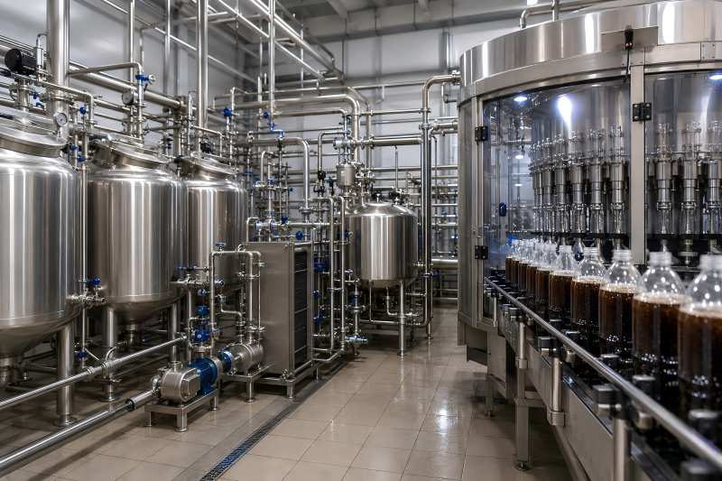
The buffer tank separates small differences between beverage preparation and filling. It stores enough product to keep the filler operating while the upstream system adjusts its output.
Without buffering, even a brief change in blending flow could affect filler pressure.
A larger tank is not necessarily the better choice. Excessive storage increases product residence time and may allow the beverage temperature to rise. Long holding periods can also increase flavor loss, ingredient separation, or microbiological risk.
A useful buffer should provide enough time for process stabilization without becoming long-term storage.
| Filling Line Output | Example Buffer Volume | Approximate Holding Time |
| 3,000 L/h | 300–600 L | 6–12 minutes |
| 8,000 L/h | 800–1,500 L | 6–11 minutes |
| 15,000 L/h | 1,500–3,000 L | 6–12 minutes |
| 25,000 L/h | 2,500–5,000 L | 6–12 minutes |
These figures are for planning reference and should be adjusted to actual operating conditions. The final volume should consider filler speed variation, cleaning strategy, product sensitivity, and restart time.
Temperature Connects Mixing with Filling
Carbonated beverages are normally cooled before CO₂ is added. Colder liquid can retain carbon dioxide more effectively and usually produces less foam during filling.
The syrup itself may be prepared at an elevated temperature, especially when sugar is dissolved with heat. Sending warm syrup directly toward the carbonator would increase the cooling load and create an unstable process.
The product temperature should therefore be reduced in a controlled way before carbonation. A heat exchanger is commonly placed after blending.
An example process may use the following temperature profile:
| Process Point | Example Temperature |
| Simple syrup preparation | 60–80°C |
| Finished syrup after mixing | 25–45°C |
| Beverage after blending | 15–30°C |
| Beverage after cooling | 2–6°C |
| Beverage at filler inlet | 3–7°C |
Temperature variation at the filler inlet should be minimized. A beverage entering at 4°C may fill smoothly, while the same product at 9°C may release more CO₂ and create foam.
The filler cannot fully compensate for unstable beverage temperature. Upstream cooling must therefore be designed for peak line capacity, not average production.
Carbonation Between Mixing and Filling
Carbonation typically occurs after the syrup and water have been blended. Carbon dioxide is introduced under controlled pressure so it dissolves into the cold beverage.
The target carbonation level depends on the product. Light sparkling water may use a lower CO₂ concentration, while certain sodas require stronger carbonation.
An illustrative range may look like this:
| Beverage Type | Example CO₂ Volume Range |
| Light sparkling water | 1.5–2.5 volumes |
| Flavored sparkling water | 2.0–3.0 volumes |
| Carbonated juice drink | 2.0–3.2 volumes |
| Standard soft drink | 3.0–4.2 volumes |
| High-carbonation soda | 4.0–4.8 volumes |
A “volume” of CO₂ describes the volume of gas dissolved in one volume of liquid under defined conditions.
Once carbonation is completed, the beverage must remain under suitable pressure until it reaches the filling valve. Sudden pressure drops, long transfer lines, sharp pipe bends, warm sections, or oversized pumps can encourage gas breakout.
Product Piping and Transfer Design
The piping between the mixing system and filling line should maintain hygienic and stable product transfer.
Important design factors include:
- Short and direct pipe routing
- Suitable pipe diameter
- Low product velocity where foaming is a concern
- Hygienic valves and fittings
- Minimum dead zones
- Insulated or cooled piping
- Controlled pump speed
- Stable back pressure
- CIP-compatible construction
An undersized pipe increases velocity and pressure loss. An oversized pipe increases product hold-up and cleaning volume. The correct pipe size balances flow, pressure stability, cleaning performance, and product residence time.
Pump selection is also important. A pump that generates excessive shear or pressure fluctuation may disturb carbonation. Variable-frequency control allows the pump speed to follow actual filler demand.
How the Control System Links Both Sections
Modern beverage plants connect the syrup room, blender, carbonator, buffer tank, and filler through a common control system.
Selecting a recipe automatically loads all required process settings:
- Syrup-to-water ratio
- Ingredient quantities
- Brix target
- Product temperature
- Carbonation level
- Tank level limits
- Transfer pressure
- Filling speed
- Cleaning sequence
The control logic should prevent unsuitable product from reaching the filler. For example, transfer may be blocked when Brix, temperature, or carbonation falls outside the accepted range.
This is more effective than relying on operators to notice a problem after bottles have already been filled.
A useful control strategy includes three response levels:
- Correction:Adjust flow, temperature, or pressure automatically.
- Warning:Alert the operator before product quality moves outside the target range.
- Interlock:Stop product transfer when the deviation could create unacceptable bottles.
The goal is not to stop the line for every small variation. It is to correct normal disturbances while preventing serious quality failures.
Preventing Flavor Changeover Losses
One filling line can process multiple carbonated beverage varieties. Each changeover leaves some product inside tanks, pipes, filters, carbonators, and filler bowls.
Poor coordination between mixing and filling can create large transition losses. The next syrup batch may be ready too early, while the previous beverage remains inside the line.
A planned changeover should consider:
- Remaining product in the syrup tank
- Product volume in connecting pipes
- Carbonator hold-up
- Buffer tank level
- Filler bowl volume
- Number of bottles required to empty the system
- Water or product used for pushing
- CIP preparation time
The production plan should reduce the buffer tank level before the final bottles of a batch are filled. This avoids leaving a full tank of finished beverage when the filler changes products.
Capacity Planning for the Complete System
The syrup room should not be sized only according to the filling machine’s maximum hourly output. Mixing time, cleaning time, testing, transfer, and product changeovers must also be included.
Consider a filler producing 15,000 liters per hour. A syrup batch may require:
- 25 minutes for ingredient loading
- 20 minutes for mixing
- 10 minutes for quality testing
- 15 minutes for transfer
- 30 minutes for cleaning and preparation
The total cycle is 100 minutes. If only one preparation tank is available, it may struggle to supply continuous production.
Using two alternating tanks allows one batch to feed the line while the next batch is being prepared. This arrangement often provides better continuity than installing one very large tank.
Capacity should therefore be based on the complete operating cycle rather than tank volume alone.