
Integrate an industrial labeling machine by agreeing on container condition, conveyor transfers, production rates, control signals, and fault handling before the equipment layout is finalized. The labeler must work through normal starts, stops, and downstream congestion as well as steady production. Define responsibility for each interface so that no essential function falls between supplier scopes.
This matters when adding a labeler to an existing line and when purchasing a complete installation. A station that performs well on its own may receive poorly spaced bottles or remain blocked by a slower packer. Integration turns separate machine capabilities into a usable production process.
Where Should the Labeler Sit in the Process?
Place the labeler where the container has the condition required by the chosen decoration process. Confirm filling, capping, inspection, conditioning, coding, and packing requirements as a complete sequence. There is no single arrangement that fits every beverage, container, and label construction.
For a water project, BRENU’s water bottling process from treatment to packing provides a starting process map. Adapt that map to the actual site and packaging specification. Do not use a generic diagram as the final installation drawing.
If the container arrives wet or outside the approved label application conditions, resolve that before commissioning. Adding speed or changing labeler settings cannot reliably substitute for a compatible incoming package. Define who supplies and validates any required surface-conditioning step.
What Information Belongs on the Layout Drawing?
Show the equipment footprint, conveyor centerlines, travel direction, transfer elevations, and service clearances. Include operator access to reels, controls, format parts, and inspection points. Maintenance access and material delivery routes need physical space even when they are absent from a simplified sales illustration.
Record the installation constraints that could affect the design. These may include columns, drains, doors, ceiling limitations, and existing utility routes. Verify dimensions on site before treating a proposed arrangement as buildable.
When reviewing BRENU’s industrial labeling machines, request a configuration-specific drawing. The space needed for a wrap-label application can differ from a double-sided or sleeve system. Include auxiliary equipment and the normal roll-loading activity in the review.
How Do You Match the Labeler to the Filler?
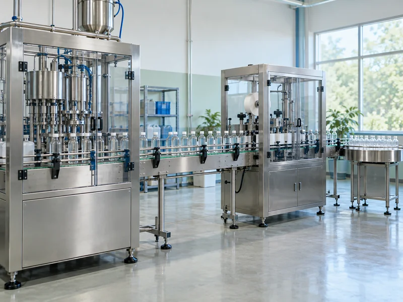
Match usable rates and transfer behavior rather than comparing headline speed figures alone. Identify the expected bottle rate for each format and the upstream pattern during startup, normal running, and recovery. The same average flow can arrive as a smooth stream or as uneven groups.
For a monoblock filling machine feeding the labeler, agree on where responsibility for spacing and stabilization begins. Confirm how container orientation is established when artwork must align with a handle, molded panel, or other feature. A plain round wrap may need a different handling arrangement from an oriented front-and-back application.
An illustrative line might fill at 120 bottles per minute while the labeler is capable of a higher agreed rate. That extra capacity may support recovery after a brief interruption, but only if container handling and the downstream process permit it. Capacity margin by itself does not create a functioning buffer strategy.
How Much Accumulation Is Useful?
Estimate accumulation from the interruptions you intend to absorb, then check whether the containers can tolerate the proposed handling. At 120 bottles per minute, a one-minute interruption represents 120 bottles of flow. This arithmetic is only the starting point for a physical accumulation design.
Usable buffer capacity depends on the actual layout, control strategy, container stability, and operating occupancy. A table advertised to hold a certain number of bottles may have less available capacity when production is already running. Ask the supplier to identify the working range rather than only the maximum physical quantity.
Also consider how the buffer is emptied after recovery. If upstream and downstream stations resume at identical rates, accumulated product may remain in the buffer. Agree on any temporary recovery rate and verify that it preserves label quality and downstream stability.
Which Control Signals Need to Be Defined?
Define the operational states and signals in a written interface schedule. Typical discussion points include ready, running, faulted, starved, blocked, and stop requests. The final signal set and implementation belong to the controls design for the actual equipment.
| Operating Event | Response to Agree | Evidence During Testing |
| Labeler cannot accept bottles | Upstream flow is managed without an uncontrolled buildup | Observed stop and recovery sequence |
| Packer stops | Accumulation and labeler discharge respond as designed | Buffer behavior and container condition |
| Labels run out | Affected product is managed by the agreed procedure | Alarm, stop, or reject response |
| Power or control interruption | Restart follows the approved operating sequence | Controlled recovery demonstration |
Keep ordinary production signals distinct from safety functions. A “ready” signal does not by itself establish that a protective function is correctly designed. The responsible integration and safety teams need to review the complete installation.
OSHA’s machine guarding guidance identifies common moving-machine hazards. Apply the relevant requirements and risk assessment to transfers and access points as well as individual stations. Connecting two guarded machines can still create an interface that needs review.
How Should Inspection and Reject Handling Be Coordinated?
Define what the line must detect and what happens to each affected container. Missing labels, incorrect artwork, placement defects, and code problems are separate inspection requirements. Do not assume one sensor or camera checks all of them.
Specify reject confirmation, collection capacity, access, and the procedure for clearing a fault. If the chosen response is a controlled stop instead of automatic rejection, document how affected product is identified. The objective is a complete handling method, not merely an alarm on the screen.
Place inspection where it can assess the required finished condition. A check before a sleeve tunnel, for example, cannot confirm the final post-shrink appearance. Agree on inspection boundaries with the packaging and quality teams.
What Changes With Carbonated or Conditioned Containers?
The incoming package may need closer review when temperature and moisture vary through the production cycle. Record the actual state at the proposed labeler entrance. Include startup and prolonged-stop conditions in the assessment rather than only a steady-state sample.
The carbonated drink filling line process is relevant when mapping those stages. Confirm whether an upstream treatment changes the package before decoration. Any conditioning equipment must be included in the layout, utilities, and acceptance scope.
Avoid making a general claim that one label technology is suitable for every cold or damp container. Suitability depends on the specified materials and process. Request a trial that reproduces the expected conditions closely enough to support the purchase decision.
How Does the Packer Affect Labeling Performance?
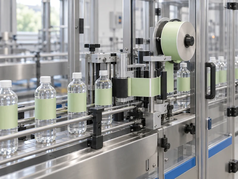
The packer determines how quickly labeled containers can leave the station and how they are handled afterward. Convert packer output into bottles per minute using the actual pack format. A machine producing 15 six-bottle packs per minute handles 90 bottles per minute, before accounting for its operating losses.
Review the alternatives in shrink wrapping versus carton packing when defining that interface. Confirm the required grouping, lane arrangement, and accumulation method. A change in secondary packaging can require a different discharge arrangement even when the labeler remains suitable.
Check the decorated container after it passes through the chosen packing route. Scuffing or label movement discovered only at the finished pallet can be expensive to isolate. Retain samples at intermediate stages during commissioning to support diagnosis.
How Should Responsibilities Be Divided Between Suppliers?
Create an interface list naming the party responsible for design, supply, installation, and testing at each boundary. Conveyor transfers, signal exchange, conditioning, inspection, and operator access are useful starting points. A component supplied by one party may still require information or testing from another.
For an existing line, identify who is authorized to modify the current controls and drawings. Confirm the changes required before arranging installation dates. Discovering a missing control interface after the new labeler arrives can delay commissioning even when the mechanical equipment is ready.
Use one current layout and one agreed interface schedule during reviews. Record changes and their effects on utilities, access, and performance assumptions. This does not need to become a large administrative exercise; the practical aim is to give each unresolved item an owner and a verifiable completion condition.
What Should the Integrated Acceptance Test Include?
Test the complete line with agreed production formats, materials, and operating conditions. Include steady output, normal interruptions, recovery, inspection responses, and a representative changeover. Record accepted containers at the agreed boundary rather than adding together unrelated station capacities.
Assign ownership of every unresolved interface before shipment or site installation. The handover should include drawings, signal definitions, setup information, and procedures for operating the connected equipment. Clear integration records make both commissioning and later troubleshooting more efficient.
Send BRENU the current layout, product matrix, upstream and downstream machine details, and the required accepted output. Ask for a written boundary-of-supply review alongside the equipment proposal. That review is the practical foundation for a line that behaves predictably during everyday production.