
Caps may look like a small part of a mineral water production line, but they directly influence sealing quality, bottle appearance, product safety, and line efficiency. A poorly matched cap or capping head can cause leakage, loose closures, damaged threads, cap deformation, and frequent machine stoppages.
Start with the Bottle Neck Finish
The bottle neck finish is the first factor to confirm before choosing a cap. It includes the neck diameter, thread shape, thread height, support ring position, sealing surface, and tamper-ring locking structure.
Two caps with a similar outside diameter may still be incompatible. Small differences in thread angle or neck height can prevent the cap from reaching the correct sealing position.
Key Neck Dimensions to Check
The following measurements should be confirmed using bottle drawings or physical samples:
- Outer diameter of the neck thread
- Inner diameter of the bottle opening
- Total neck height
- Thread pitch
- Number of thread starts
- Sealing surface width
- Support ring diameter
- Tamper-ring locking diameter
- Distance between the sealing surface and support ring
The bottle supplier should provide an accurate neck drawing. When a drawing is unavailable, several samples should be measured because blow-molded PET bottles may have small dimensional variations.
| Inspection Item | Typical Practical Tolerance | Possible Problem if Incorrect |
| Neck outer diameter | ±0.10–0.20 mm | Cap too tight or too loose |
| Neck height | ±0.15–0.30 mm | Poor sealing or excessive pressure |
| Thread position | ±0.15 mm | Cross-threading |
| Sealing surface flatness | Within 0.10–0.20 mm | Water leakage |
| Support ring position | ±0.20 mm | Unstable bottle handling |
| Tamper-ring locking diameter | ±0.10–0.20 mm | Ring breaks early or remains attached |
These figures are useful engineering references rather than universal standards. The acceptable tolerance depends on the cap weight, neck design, bottle speed, and sealing method.

Match the Cap Type to the Mineral Water Product
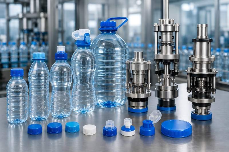
Most still mineral water bottles use lightweight plastic screw caps. However, the appropriate cap structure changes with bottle size, distribution conditions, opening experience, and packaging position.
1. Standard Screw Caps
Standard screw caps are widely used for small and medium-sized PET water bottles. They are simple, economical, and suitable for high-speed filling lines.
They usually include:
- A threaded cap body
- An internal sealing structure
- A tamper-evident band
- Small bridges connecting the band to the cap
- External knurling for gripping
This design works well for common retail bottles when the bottle neck and cap are accurately matched.
2. Lightweight Short-Height Caps
Lightweight caps reduce plastic consumption and packaging cost. They also reduce the amount of material used in the bottle neck because a shorter cap often works with a shorter neck finish.
However, lightweight caps usually have a smaller operating window. Their reduced wall thickness makes them more sensitive to excessive torque, poor cap feeding, high temperature, and uneven pressure from the capping head.
A factory moving from a conventional cap to a lightweight cap should not assume that the existing capping head will work without adjustment.
3. Sports Caps
Sports caps are suitable for mineral water bottles used during exercise, travel, or outdoor activities. They may include push-pull or flip-top structures.
These caps are more complex than ordinary screw caps and may require:
- Special cap elevators
- Orientation systems
- Dedicated chutes
- Shape-matched capping heads
- Additional closure inspection
Sports caps also need more headroom and may not move smoothly through a chute designed for flat caps.
4. Large-Bottle Caps
Bottles with capacities such as 3, 5, 10, or 20 liters normally use larger and stronger closures. The cap must withstand greater handling stress because large bottles are heavier and may experience more movement during transportation.
Large caps often need higher application torque, stronger capping heads, and more stable bottle positioning.
Understand the Cap Sealing Structure
A cap does not seal the bottle only through thread tightening. The actual seal is normally formed by contact between an internal cap feature and a specific area of the bottle neck.
Common sealing structures include plug seals, linerless seals, and caps with separate sealing liners.
1. Plug Seal
A plug seal enters the inner opening of the bottle neck. It creates a seal by pressing against the internal wall.
This design can provide reliable leakage protection, but it depends heavily on the inner diameter and roundness of the neck opening. An oval or damaged bottle opening may reduce sealing performance.
2. Outer-Lip Seal
An outer-lip structure seals against the top or outer edge of the bottle neck. It may be less sensitive to small internal-diameter variations, but the top sealing surface must remain clean and even.
Water droplets, neck damage, or particles on the sealing surface can create leakage paths.
3. Combined Seal
Some caps use more than one contact point. For example, an internal plug may work together with a top lip.
A combined seal can increase reliability, but it may also require tighter dimensional control. Too much interference can increase removal torque or deform the bottle neck.
4. Lined Caps
A lined cap contains a separate sealing material inside the closure. It can improve sealing under certain conditions, but it adds material, complexity, and cost.
For standard still mineral water, a properly designed linerless cap is often sufficient. Lined caps are more relevant when the packaging requires special chemical resistance, extended storage, or additional barrier performance.
Choose the Correct Cap Material
Most mineral water caps are made from high-density polyethylene or polypropylene. The choice affects flexibility, dimensional stability, torque behavior, and opening feel.
1. High-Density Polyethylene
High-density polyethylene caps are relatively flexible and can perform well on high-speed water lines. Their flexibility allows the thread and tamper band to move slightly during application.
They are often suitable for lightweight closures and can provide a comfortable opening experience.
2. Polypropylene
Polypropylene is generally stiffer. It can provide good dimensional stability and a clear opening feel, but an overly rigid cap may be less forgiving when bottle neck dimensions vary.
The material decision should be based on the complete cap design rather than resin type alone.
| Cap Factor | More Flexible Material | More Rigid Material |
| Tolerance to neck variation | Usually higher | Usually lower |
| Dimensional stability | Moderate | Higher |
| Resistance to deformation | Moderate | Higher |
| Torque sensitivity | Often lower | Often higher |
| Opening feel | Softer | More defined |
| Suitability for thin caps | Good with proper design | Depends on wall thickness |
Recycled content, color masterbatch, cooling conditions, and molding quality can also change cap performance. Caps made from the same base resin may behave differently when produced by different suppliers.
Evaluate the Tamper-Evident Band
The tamper-evident band shows whether the bottle has been opened. It is an important quality and consumer-confidence feature.
During capping, the band passes over a locking ring on the bottle neck. During opening, the bridges should break while the band remains below the neck ring or separates in a controlled way.
Common Tamper-Band Problems
A band may break during capping when:
- The locking diameter is too large
- The band is too rigid
- The bridges are too weak
- The cap is applied at an angle
- The cap temperature is too low
- The capping head applies excessive downward pressure
A band may fail to break during opening when:
- The bridges are too strong
- The neck locking ring is too small
- The band stretches instead of breaking
- The cap is not fully applied
- The cut depth around the band is insufficient
The tamper band should be tested after filling, after storage, and after transportation simulation. A cap that works immediately after production may perform differently after several days because the plastic can relax.
Select the Capping-Head Type
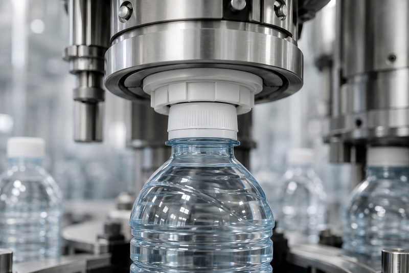
The capping head transfers rotational force and downward pressure to the cap. Its design should match the cap geometry, machine speed, and required torque accuracy.
1. Magnetic-Torque Capping Heads
Magnetic-torque heads use magnetic force to limit the transmitted torque. When the resistance reaches the selected value, the internal mechanism slips.
Their advantages include:
- Relatively stable torque
- Simple mechanical structure
- Good suitability for standard screw caps
- Easy torque adjustment
- Protection against excessive tightening
They are widely used on mineral water filling machines because they provide a practical balance between cost and performance.
However, magnetic heads still require regular inspection. Worn components, contamination, incorrect adjustment, or temperature changes can affect performance.
2. Mechanical-Clutch Capping Heads
Mechanical-clutch heads use springs, friction components, or clutch mechanisms to control torque. They can be effective, but friction surfaces may change as they wear.
They should be checked frequently when the line operates continuously. Variations between heads can become noticeable if maintenance is inconsistent.
3. Servo Capping Heads
Servo capping systems use controlled motors to manage rotation, speed, angle, and torque. They can provide detailed production data and precise adjustment.
They are useful when:
- Several cap types are handled
- Fast product changeover is required
- Torque traceability is important
- The cap has a complex application profile
- The factory wants automatic recipe control
Servo systems usually involve higher investment and more complex controls. For a plant producing one standard bottle format, a well-maintained magnetic capping system may be more economical.
Match the Head Insert to the Cap Shape
The capping-head insert, sometimes called the chuck or gripper, directly contacts the cap. It must grip the closure securely without damaging the knurling or deforming the cap body.
The insert should match:
- Cap outside diameter
- Cap height
- Knurl pattern
- Top surface shape
- Cap wall strength
- Required gripping depth
A loose insert may slip and create low torque. An overly tight insert may scratch the cap, distort the sidewall, or prevent smooth cap release.
Flexible liners can improve grip, but they wear over time. A worn liner often causes unstable torque before the damage becomes visually obvious.
Determine the Correct Application Torque
Application torque is the rotational force used to tighten the cap. Too little torque causes loose caps and leakage, while too much torque may damage the thread, sealing structure, or tamper band.
The ideal setting is not simply the highest torque the cap can withstand. It should be the lowest stable torque that produces reliable sealing under expected production and distribution conditions.
| Cap Application | Example Application-Torque Range | Main Selection Concern |
| Lightweight small water cap | 8–14 N·cm | Avoid cap deformation |
| Standard small PET water cap | 10–18 N·cm | Balance sealing and opening |
| Medium bottle closure | 14–24 N·cm | Control head-to-head variation |
| Large water-bottle cap | 20–40 N·cm | Prevent loosening during transport |
| Specialty or sports cap | Supplier-specific | Protect moving cap components |
These values are illustrative engineering ranges. Final settings must be established through cap, bottle, leakage, opening, and transport tests.
Application Torque and Removal Torque Are Different
Application torque is measured during capping. Removal torque is measured when the cap is opened later.
Removal torque may decrease after several hours because the plastic cap and bottle neck relax. Temperature can also change the result.
For example, a cap applied at 15 N·cm may have a removal torque of approximately 9–13 N·cm after 24 hours. The exact relationship depends on the cap material, neck finish, sealing interference, and storage temperature.
Control Downward Pressure
A capping head normally applies downward force while rotating the cap. This pressure helps the thread engage and allows the tamper band to move over the bottle neck ring.
Excessive pressure can:
- Deform lightweight bottles
- Damage the cap top
- Force the cap into cross-threading
- Break tamper-band bridges
- Overload bottle-handling parts
Insufficient pressure may prevent full thread engagement. The cap may rotate without reaching its final sealing position.
Lightweight bottles usually require better bottle support. Neck-handling components, guide rails, and lifting mechanisms should keep the bottle stable during capping.
Consider Production Speed
A cap that performs well at 3,000 bottles per hour may not behave the same at 24,000 bottles per hour. Higher speeds reduce the time available for cap pickup, alignment, thread engagement, tightening, and release.
Speed-Related Selection Factors
At higher production rates, the cap should have:
- Stable dimensions
- Consistent roundness
- Reliable knurling
- Low tendency to stick together
- Strong but flexible tamper bands
- Smooth chute movement
- Predictable thread engagement
The capping head should also support the required rotational speed without excessive vibration or heat.
| Line Speed | Recommended Evaluation Focus |
| Below 3,000 bottles/hour | Basic compatibility and manual adjustment |
| 3,000–8,000 bottles/hour | Stable cap feeding and torque control |
| 8,000–18,000 bottles/hour | Head consistency and bottle stabilization |
| 18,000–30,000 bottles/hour | High-precision cap orientation and handling |
| Above 30,000 bottles/hour | Full-system control, inspection, and rapid rejection |
Rated machine speed should not be confused with stable production speed. A line may reach its nominal output for a short test but operate poorly during an eight-hour shift if cap quality is inconsistent.
Check the Cap Feeding System
Selecting the right cap and capping head is not enough. The cap must also move reliably from the hopper to the bottle.
The feeding system normally includes:
- Cap hopper
- Elevator
- Sorting device
- Orientation track
- Chute
- Cap-present sensor
- Cap transfer mechanism
A tall, light, or irregularly shaped cap may overturn inside the chute. Caps with soft sidewalls may become nested together, while excessive static electricity can cause lightweight closures to stick.
The cap supplier should provide enough samples for a full-speed feeding test. Testing only a few hundred caps may not reveal occasional jams.
Account for Filling Temperature and Environment
Mineral water is normally filled at a relatively low or ambient temperature. Even so, environmental conditions can influence capping performance.
Cold caps may become less flexible. Hot storage conditions may soften the material, while high humidity or water spray can reduce friction between the cap and the capping-head insert.
The following conditions should be considered:
- Cap warehouse temperature
- Filling-water temperature
- Rinsing-water contact
- Humidity around the filler
- Seasonal factory temperature
- Time between cap molding and use
- Exposure to direct sunlight
Caps and bottles should ideally reach a stable production-room temperature before testing. Results from cold warehouse samples may not represent normal operation.
Measure Head-to-Head Variation
Multi-head cappers may contain several capping heads. Even when the average torque is acceptable, one head may apply too little torque while another applies too much.
Suppose a 12-head capper produces the following result:
| Measurement | Torque Result |
| Target torque | 15 N·cm |
| Lowest head average | 11.8 N·cm |
| Highest head average | 18.6 N·cm |
| Overall average | 15.2 N·cm |
| Head-to-head spread | 6.8 N·cm |
The overall average looks correct, but the spread is too wide. Some bottles may leak while others are difficult to open.
Each head should therefore be identified and tested separately. Maintenance records should show which head was adjusted, repaired, or replaced.
Balance Sealing Performance with Consumer Opening
A tightly sealed bottle is not automatically a successful package. Consumers must also be able to open it without excessive effort.
Opening difficulty can be caused by:
- Excessive application torque
- High seal interference
- Aggressive thread design
- Rigid cap material
- Deep knurling
- Cap deformation
- Tamper bridges that are too strong
Children, older users, and consumers with limited grip strength may struggle with a cap that passes factory leakage tests but requires excessive opening force.
Cap development should therefore balance production security with consumer convenience.
Review Supplier Consistency
Cap quality should be evaluated across several production batches. A supplier may provide excellent trial samples but later deliver caps with different weight, dimensions, color, or material behavior.
Important supplier controls include:
- Resin traceability
- Cap-weight consistency
- Dimensional inspection
- Tamper-band cutting control
- Color consistency
- Contamination prevention
- Batch identification
- Packaging protection
- Change-notification procedures
A cap-weight reduction of only 0.1 gram can be commercially valuable across millions of bottles. However, the saving is not worthwhile if it increases leakage, deformation, or line stoppages.