
A carbonated drink filling line can occupy several hundred to several thousand square meters. The correct figure depends on output, packaging, storage strategy, utility placement, and the level of automation.
For a small production line, 250 to 450 square meters may be workable. A medium line often requires 600 to 1,200 square meters. A large automated plant may require more than 2,000 square meters once warehouses and supporting rooms are included.
Typical Space Requirements by Line Capacity
Production speed is usually the first factor considered during layout planning. Higher output requires larger machines, longer conveyors, more packaging equipment, and wider material-handling areas.
| Nominal Line Speed | Typical Application | Main Production Area | Estimated Total Factory Area |
| 2,000–4,000 bottles/hour | Small local beverage plant | 120–200 m² | 250–450 m² |
| 6,000–10,000 bottles/hour | Regional beverage production | 250–450 m² | 500–900 m² |
| 12,000–18,000 bottles/hour | Medium industrial plant | 400–700 m² | 800–1,400 m² |
| 20,000–30,000 bottles/hour | Large automated factory | 650–1,100 m² | 1,300–2,300 m² |
| Above 36,000 bottles/hour | High-volume beverage facility | 1,000–1,800 m² | 2,000–4,000 m² or more |
The main production area includes the container-forming, filling, labeling, packing, and conveying sections. The total factory area also includes preparation rooms, warehouses, laboratories, utility systems, offices, passages, and maintenance zones.
A line should not be selected only because its machines physically fit inside the building. A tightly packed line may be difficult to clean, inspect, repair, or expand.
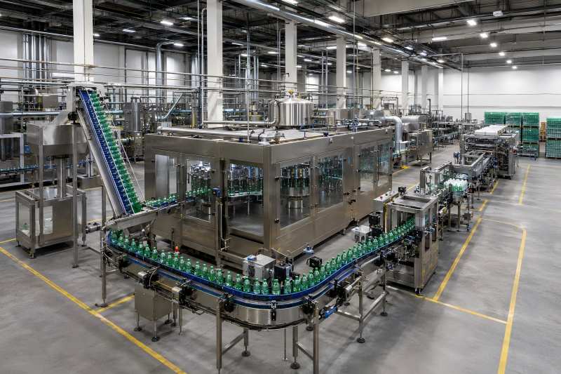
The Filling Section Is Only Part of the Complete Production Space
The rinser-filler-capper is normally the central machine, but it may account for only 10% to 20% of the complete production footprint.
A 10,000-bottle-per-hour monoblock may occupy approximately 20 to 35 square meters. However, the connected equipment may extend the operating line to a length of 35 to 60 meters.
A complete PET bottle line can include:
- Preform feeding and bottle blowing
- Air conveying
- Empty-bottle inspection
- Rinsing, filling, and capping
- Cap feeding
- Bottle drying
- Labeling
- Coding
- Shrink wrapping or carton packing
- Palletizing
- Full-bottle conveying
- Inspection and rejection stations
Each machine requires its own operating footprint. Additional space must be reserved around it for doors, control cabinets, product pipes, change parts, cleaning, and maintenance.
Main Areas That Determine the Factory Footprint
Bottle Blowing Area
A PET bottle line may include an integrated or separate blow molding system. The blowing area requires space for the blow molder, preform hopper, preform elevator, air compressor connections, mold-change access, and bottle transfer.
A small blow molding section may require 40 to 80 square meters. A high-speed rotary blow molding area can require 100 to 250 square meters.
Producing bottles inside the factory reduces empty-bottle storage, but it increases utility demand and equipment complexity. Purchasing finished bottles requires less production equipment but much more warehouse space because empty PET bottles occupy a large volume.
Beverage Preparation Room
Carbonated drinks require controlled preparation before filling. A typical system may include sugar dissolving, syrup filtration, blending, cooling, deaeration, and carbonation.
The preparation room should be separated from dry packaging materials and heavy warehouse traffic. A compact system may require 50 to 100 square meters, while a multi-tank preparation system may require 150 to 350 square meters.
Tank height also affects building requirements. A floor area may appear sufficient while the ceiling is too low for tank installation, pipe routing, platforms, or top-mounted agitators.
Water Treatment Section
Water treatment equipment can include raw-water tanks, sand filters, activated-carbon filters, softeners, reverse-osmosis units, ultraviolet sterilizers, and treated-water storage tanks.
Small systems may fit within 30 to 60 square meters. Larger systems may require 100 square meters or more, especially when several storage tanks are installed.
Enough access should be left for membrane replacement, filter servicing, chemical dosing, and sanitation.
Filling and Conveying Area
The filling room should be treated as a controlled production zone. It includes the main filling monoblock, bottle infeed, bottle discharge, cap sterilization, inspection devices, and connected conveyors.
The equipment itself may fit in a narrow space, but the surrounding access is equally important. A practical design normally provides at least 1 to 1.5 meters of working clearance around frequently serviced sides.
Larger maintenance doors may require 2 meters or more of open space. This area must remain free from columns, drains, pipes, and neighboring machines.
Secondary Packaging Area
Secondary packaging often consumes more floor space than expected. Shrink wrappers, carton erectors, case packers, handle applicators, case sealers, palletizers, and stretch wrappers create a long downstream section.
| Packaging Method | Relative Space Requirement | Main Layout Impact |
| Film shrink wrapping | Low to medium | Compact but needs a shrink tunnel |
| Tray and film packing | Medium | Requires tray feeding and film storage |
| Carton case packing | Medium to high | Needs carton forming and sealing space |
| Robotic case packing | High | Requires guarded robot operating area |
| Automatic palletizing | High | Needs pallet handling and safety fencing |
A simple shrink-pack section may require 40 to 80 square meters. An automatic carton-packing and palletizing system may require 150 to 350 square meters.
Packaging materials must also be delivered to the machines without crossing the wet filling zone.
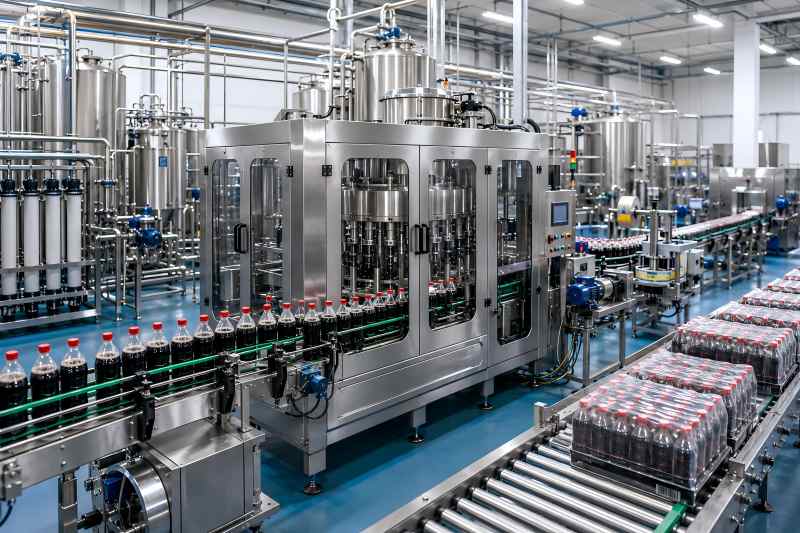
Space for Conveyors and Buffering
Conveyors do more than connect machines. They stabilize production by creating accumulation between machines with different operating patterns.
Without enough conveyor buffer, a short labeler stoppage may force the filling machine to stop immediately. Excessive buffer, however, increases floor-space use and can create bottle pressure or instability.
For a medium-speed line, conveyors may account for 25% to 40% of the main production area.
A straight-line layout uses space efficiently when the building is long and narrow. An L-shaped or U-shaped layout may fit a shorter building, but turning conveyors and corner transfers add complexity.
The correct layout should balance compactness with smooth bottle flow. Eliminating every conveyor section may reduce the initial footprint but increase line stoppages.
Storage Space Can Exceed Production Space
A beverage plant requires space for raw materials, packaging materials, spare parts, finished products, and rejected goods.
Typical stored materials include:
- Preforms or empty bottles
- Caps
- Labels
- Film rolls
- Carton blanks
- Sugar and ingredients
- Cleaning chemicals
- Lubricants
- Spare and change parts
Finished products usually require the largest warehouse area. A line producing 10,000 bottles per hour can produce 80,000 bottles during an eight-hour shift.
If 24 bottles are packed per case, this equals approximately 3,333 cases per shift. Holding three days of production requires space for about 10,000 cases, depending on pallet height and shipping frequency.
A factory with frequent truck collection may need less finished-product storage. A plant serving seasonal demand may need a warehouse much larger than the production hall.
Maintenance and Operator Access
Machines should never be installed directly against walls simply to reduce the footprint. Service technicians need room to remove motors, star wheels, filling valves, electrical cabinets, conveyor chains, and guards.
Practical access planning may include:
- 0–1.2 meters for normal operator passages
- 2–1.5 meters around service sides
- 5–2.5 meters near major component-removal points
- 5–4 meters for forklift or pallet movement
- Dedicated escape routes that remain unobstructed
Access requirements should be reviewed for every machine rather than applied as one general distance. A control-panel side may need less space than a side where molds or large star wheels are removed.
Overhead access also matters. Pipe racks, cable trays, ventilation ducts, and compressed-air lines should not block lifting equipment or maintenance platforms.
Utility Rooms and Supporting Systems
Carbonated beverage production depends on several supporting systems that may be located inside or outside the main production hall.
These may include:
- High-pressure air compressors
- Low-pressure air compressors
- Air dryers and receivers
- Chillers
- CO₂ supply and pressure regulation
- Steam or hot-water systems
- Electrical distribution
- Cleaning-in-place systems
- Wastewater collection
- Backup power equipment
Utility equipment can require 8% to 15% of the total factory area. Outdoor installation can save indoor space, but weather protection, noise, maintenance, and pipe distance must be considered.
Compressors should normally be separated from sensitive production areas because they generate noise and heat. Chillers also need sufficient ventilation and service access.
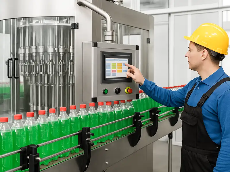
Example Layout for a 10,000-Bottle-per-Hour Line
The following example illustrates a PET carbonated drink line with bottle blowing, automatic filling, labeling, shrink packing, and semi-automatic pallet handling.
| Factory Section | Example Area |
| Water treatment | 55 m² |
| Syrup preparation and carbonation | 110 m² |
| Bottle blowing | 75 m² |
| Filling room | 120 m² |
| Labeling and packaging | 100 m² |
| Utility room | 60 m² |
| Packaging-material storage | 90 m² |
| Finished-product storage | 180 m² |
| Laboratory and spare-parts room | 35 m² |
| Passages and maintenance clearance | 125 m² |
| Total | 950 m² |
The equipment may technically fit into 500 to 600 square meters, but the larger 950-square-meter plan creates better maintenance access, safer traffic flow, and more usable storage.
A factory intended to run continuously should prioritize operating space over minimum installation space.
How Bottle and Packaging Formats Change Space Needs
A line handling one bottle size can be relatively compact. A line handling several bottles, labels, caps, and pack formats requires additional space for change parts and material staging.
Glass bottles also change the layout. They are heavier, less tolerant of impact, and often require depalletizing, bottle washing, crate handling, and empty-container return areas.
Cans may use compact conveying, but they can require depalletizers, rinsers, seamers, pasteurizers, and inspection systems.
PET bottles normally provide the greatest layout flexibility. However, unstable lightweight bottles may require longer air conveyors and more controlled transfer sections.
Planning for Future Expansion
A filling line should be designed around the expected business direction rather than only the first-year output.
Useful expansion allowances include:
- 15% to 25% additional production-floor space
- Spare conveyor connection points
- Space for a future packer or palletizer
- Extra utility capacity
- Expandable electrical distribution
- Additional syrup or storage tank positions
- Reserved warehouse access
Leaving an empty rectangular expansion zone is usually more valuable than leaving several small unused spaces around the building.
Future equipment should be able to connect without relocating the entire filling line. Relocation can involve new foundations, pipe changes, electrical work, recommissioning, and extended production downtime.