
Treated-water storage should be sized against changing bottling demand, treatment output, and planned interruptions—not a fixed number of operating hours. The objective is to protect production while limiting unnecessary storage and water residence time.
Start with a time-based balance of water entering and leaving the tank, then check the usable operating range, cleaning withdrawals, refill capability, and hygiene requirements.
Establish the Design Basis
Begin with the water consumers that must be supplied from the treated-water tank. Finished-product water may be only one demand; bottle rinsing, line flushing, and cleaning can create additional withdrawals that coincide with production.
Record the bottling line’s expected operating rate, product mix, shift pattern, and planned stops.
Convert each activity into a water demand over a defined time interval, using measured consumption where available rather than treating all equipment as continuously operating at its maximum rate.
Next, establish the treatment system’s realistic output. Rated capacity alone may not describe actual production when feed-water conditions, pretreatment, membrane operation, regeneration, maintenance, or other operating constraints reduce available output.
The design basis should distinguish routine conditions from credible short interruptions. Include the duration of a treatment outage, the time needed to restart or stabilize treatment, and whether the line continues running during that period.
-
Inflow: Treated water delivered to storage during each interval.
-
Outflow: Product water, rinsing, flushing, and cleaning makeup withdrawn during that interval.
-
Initial inventory: The actual tank volume at the beginning of the scenario.
-
Operating limits: The lowest permitted inventory and the highest normal operating level.
-
Recovery: The time and surplus treatment capacity available to rebuild inventory before the next demand peak.
If demand is recorded in litres per bottle, convert it using the planned number of bottles and account for bottle formats or operating modes that change consumption.
Build a Time-Varying Water Balance
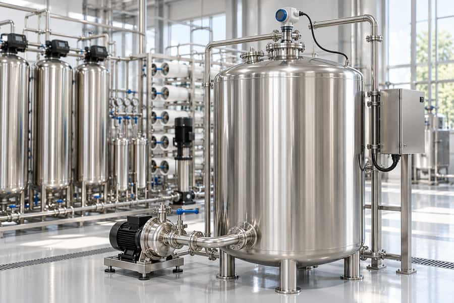
A tank is a buffer, so its required volume depends on when inflow and outflow occur, not only on daily totals.
A treatment system may produce enough water over a full shift yet fail to meet demand during a concentrated outage.
For each interval, calculate the net change as treated-water inflow minus all water withdrawn from the tank.
Add that change to the inventory at the start of the interval to determine the ending inventory, which becomes the next interval’s starting point.
Track the inventory chronologically.
Positive net change raises the tank level; negative net change draws it down.
This sequence shows whether the tank crosses its low operating limit or exceeds its maximum normal level at any point.
Illustrative operating schedule: Assume treatment supplies 7.5 m³/h when operating, while the bottling line and rinsing together withdraw 6 m³/h.
Start at 06:00 with 15 m³ in the tank.
During 06:00–08:00, treatment operates normally, so inventory increases by 1.5 m³ each hour, reaching 18 m³ at 08:00.
Now assume treatment is unavailable from 08:00 to 10:00 while production continues.
The first outage hour withdraws 6 m³, reducing inventory to 12 m³.
During the second outage hour, cleaning a separate, safely isolated circuit adds an illustrative 2 m³ of makeup demand, so total withdrawal is 8 m³ and inventory falls to 4 m³ at 10:00.
When treatment resumes at 10:00, inflow returns to 7.5 m³/h against 6 m³/h of routine demand.
Inventory therefore recovers by 1.5 m³ per hour, reaching 5.5 m³ at 11:00 and 7 m³ at 12:00.
These assumed values are for demonstrating the calculation, not a plant specification.
The example shows why a daily average is insufficient: the tank reaches its lowest inventory at the end of the outage and cleaning period, even though treatment later resumes.
The full balance must also check the highest inventory before the outage and confirm that normal controls prevent overfilling.
Define the Minimum Operating Inventory
The illustrative minimum of 3 m³ is an assumption, not a universal requirement. The tank’s low-level setting must be established from the actual pump arrangement, suction conditions, and volume that cannot be reliably delivered.
In this example, the calculated minimum inventory is 4 m³, leaving only 1 m³ above the assumed operating minimum.
That difference is the remaining margin in this scenario, not proof that the design provides sufficient protection against every possible disturbance.
Check the Complete Time-Step Balance
The following table carries the illustrative schedule forward using the same assumptions: treatment output of 7.5 m³/h when available, routine withdrawal of 6 m³/h, and an additional 2 m³ CIP makeup withdrawal during 09:00–10:00.
| Time | Operating condition | Net inventory change | Ending inventory |
| 06:00 | Initial inventory | — | 15 m³ |
| 08:00 | Two hours of normal operation | +3 m³ | 18 m³ |
| 09:00 | Treatment outage; routine demand continues | −6 m³ | 12 m³ |
| 10:00 | Outage continues; routine demand plus CIP makeup | −8 m³ | 4 m³ |
| 11:00 | Treatment resumes; production continues | +1.5 m³ | 5.5 m³ |
| 12:00 | Treatment continues; production continues | +1.5 m³ | 7 m³ |
All values are illustrative assumptions, not verified equipment specifications.
The table shows the inventory at each checkpoint, but the calculation must also consider what happens between checkpoints.
If flow rates vary within an interval, use shorter time steps or measured flow profiles to identify the actual minimum and maximum.
Do not calculate required storage by simply adding every negative interval. Positive changes between withdrawals replenish the tank, so the relevant deficit depends on the cumulative balance from the chosen starting inventory.
Separate Contingency Reserve from the Calculated Demand
A contingency reserve should address credible uncertainties that the operating scenario does not already cover. Examples include variability in treatment recovery, a longer-than-planned interruption, or a temporary increase in water demand.
First, establish the working volume required by the modeled scenario. Then identify additional risks and decide whether each requires a separate reserve, a revised scenario, or an operational control.
Do not add a generic outage allowance on top of an outage already included in the balance without checking for overlap.
Similarly, if the minimum operating inventory already accounts for the pump’s unusable volume, do not count that same volume again as a separate reserve.
A useful design review should distinguish three quantities:
-
Calculated working requirement: The storage needed to meet the modeled demand profile while respecting operating limits.
-
Operational minimum: The inventory that must remain to maintain reliable withdrawal and protect the pumping system.
-
Additional contingency: Extra capacity justified by uncertainty not already represented in the other two quantities.
There is no universally appropriate percentage for contingency or a fixed number of storage hours suitable for every bottling plant.
The allowance should follow from the consequences of a shortage, credible operating variability, and the availability of backup treatment or alternative supply.
Convert Usable Volume into Nominal Tank Capacity
Usable storage is the volume available between the normal high operating level and the minimum operating level. Nominal capacity describes the tank’s rated capacity and does not automatically equal its usable working range.
For the illustrative scenario, assume the normal high operating inventory is 18 m³ and the minimum operating inventory is 3 m³. The difference is 15 m³ of usable operating range.
The physical tank must accommodate the liquid volume corresponding to the high operating level, with sufficient freeboard below the permitted maximum level. Its geometry and operating limits determine the required nominal capacity.
Do not assume that a level percentage corresponds directly to the same percentage of tank volume.
This relationship is valid only when supported by the tank’s geometry or a suitable level-to-volume calibration.
In a horizontally mounted cylindrical tank, equal increases in liquid height do not correspond to equal increases in stored water volume.
Verify Refill Time and Repeatable Daily Operation
After the illustrative outage, inventory reaches 7 m³ at 12:00. If treatment delivers 7.5 m³/h while production continues withdrawing 6 m³/h, the net recovery rate is 1.5 m³/h.
Restoring inventory from 7 m³ to the 18 m³ high operating level requires an additional 11 m³.
At a net recovery rate of 1.5 m³/h, this takes approximately 7 hours and 20 minutes, provided those rates remain constant and no additional withdrawals occur.
The tank would therefore reach the assumed high operating level at approximately 19:20. This calculation describes the recovery period while production continues; it does not establish that the same schedule will repeat every day.
Check the next operating cycle’s starting inventory.
If the tank remains at 18 m³ overnight, the following day cannot begin at the illustrative 15 m³ starting inventory unless overnight consumption or another planned operating condition reduces it.
Recalculate the sequence using the actual overnight demand and level-control strategy.
Treatment inflow must also be capped by the system’s maximum available output and the tank’s permitted filling rate.
Once the high operating limit is reached, controls must prevent overfilling rather than assuming the tank can continue accepting the calculated surplus.
Coordinate CIP with Production and Storage Recovery
CIP makeup should be included at the time it is actually withdrawn. If cleaning coincides with the treatment outage, the combined demand may create a deeper inventory deficit than either event alone.
Allow CIP to overlap production only when the cleaning circuit is safely isolated from the product-water supply, the required water quality is maintained, and the remaining treatment and distribution capacity can support both activities.
Otherwise, schedule cleaning separately or provide a validated alternative supply arrangement.
The objective is not simply to increase tank size until every activity can occur simultaneously.
It is to establish a practical operating sequence that meets water demand, protects hygiene, and allows storage to recover before the next critical period.
Design for Sanitary Storage and Validated Residence Time
Treated-water storage must preserve the water quality established by the treatment process. Tank sizing, materials, venting, drainage, and downstream piping should therefore be assessed together rather than treating storage as a simple volume calculation.
Residence time depends on the actual inventory and withdrawal pattern.
A large tank may provide a longer interruption buffer, but it can also increase the time water remains in storage, particularly during low production or extended shutdowns.
Establish acceptable holding conditions through the plant’s water-quality requirements, sanitary design, intended use, and validation results. Each bottling plant needs to establish suitable storage time limits and microbiological criteria based on its process, water-quality requirements, and validation results.
Tank recirculation may help manage mixing or temperature where appropriately designed, but it does not reset water age or guarantee hygienic conditions. Water-quality monitoring and a validated storage strategy remain necessary.
Check Tank Drainage, Vent Protection, and Access
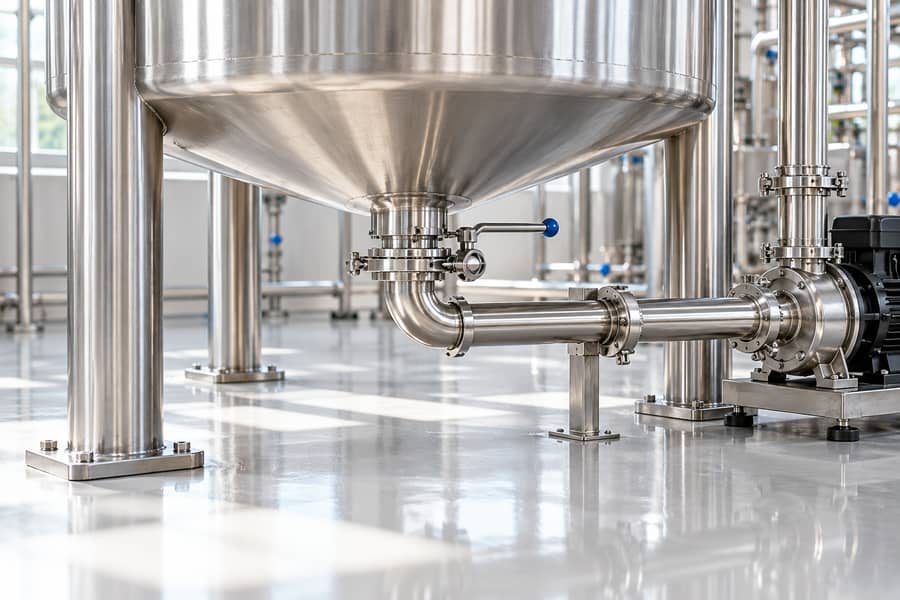
Tank construction should support effective cleaning, inspection, and maintenance. Material selection, internal surfaces, connections, and drainage arrangements should match the water quality and applicable hygienic requirements.
-
Drainage: Provide an appropriate drain arrangement that minimizes retained water and supports the approved cleaning procedure.
-
Vent protection: Evaluate the breather, filtration where required, moisture exposure, and potential routes for airborne contamination.
-
Access: Provide suitable access for inspection, cleaning, and maintenance without compromising hygienic integrity.
-
Connections: Review inlet and outlet positions, dead legs, stagnant branches, and the possibility of unintended cross-connections.
-
Materials: Confirm that wetted materials and seals are suitable for the treated water, cleaning procedure, and operating conditions.
-
Provide suitable isolation arrangements so the tank can be taken out of service safely for inspection or maintenance.
The tank’s nominal volume does not establish whether its internal design is hygienically suitable. Procurement specifications should address both capacity and the features required to maintain water quality throughout operation.
Calibrate Operating Levels and Protect Pumps
Level instrumentation must reflect the tank’s actual geometry.
A level transmitter measures liquid height or another level-related signal; the corresponding volume should be determined from a suitable calibration rather than assumed to be proportional to height.
Define the normal operating range, low-level threshold, high-level threshold, and any separate emergency limits. Confirm that the control system can distinguish routine operating levels from conditions requiring an alarm or automatic action.
Pump protection should be coordinated with the low-level settings. The minimum permitted inventory must account for suction conditions, pump submergence where applicable, and the risk of air entrainment or loss of reliable delivery.
-
Low-level alarm: Warn operators when available storage approaches the defined operating limit.
-
Pump protection: Use appropriate interlocks or shutdown logic to prevent operation under unacceptable suction conditions.
-
High-level alarm: Identify abnormal filling conditions before they lead to overflow.
-
Level verification: Compare instrument readings with an independent level or volume reference during commissioning.
-
Control response: Confirm that valves, pumps, and treatment equipment respond correctly to the specified thresholds.
Alarm and interlock settings should be established from the actual equipment and process risks. Determine alarm and interlock settings from the specific plant’s equipment and operating conditions instead of adopting settings used at another facility without reassessment.
Validate the Design Through Commissioning Stress Tests
Commissioning should demonstrate that storage performs adequately under realistic operating conditions, not merely that the tank can hold its nominal volume.
Test representative production demand, treatment interruptions, recovery periods, and planned cleaning activities. Include credible combinations of events that could reduce inventory or prevent the tank from refilling before the next production cycle.
Verify both low- and high-inventory conditions. Confirm that the tank remains within its permitted operating range, pumps retain acceptable suction conditions, and level controls prevent overfilling.
Record the actual inflow and withdrawal profiles during testing. Compare the observed inventory changes with the design balance, investigate discrepancies, and revise assumptions where measured demand or treatment output differs from the original estimates.
Water-quality release should follow the plant’s approved validation and sanitation procedures. Successful hydraulic testing alone does not establish that stored water is suitable for production.
Prepare the Procurement Input Checklist
Before requesting a quotation, consolidate the process data and operating requirements into a common specification. This helps suppliers compare equivalent designs rather than proposing tanks based on nominal capacity alone.
| Design input | Information to provide |
| Production demand | Line rate, product formats, operating hours, and water consumption |
| Treatment supply | Available output, operating schedule, downtime, and recovery constraints |
| Storage balance | Starting inventory, time-based inflows and withdrawals, and minimum permitted inventory |
| CIP requirements | Makeup demand, cleaning schedule, and whether cleaning overlaps production |
| Tank configuration | Required usable volume, permitted operating levels, freeboard, and installation constraints |
| Pumping and controls | Peak demand, suction requirements, instrumentation, alarms, and interlocks |
| Hygiene requirements | Wetted materials, drainage, vent protection, inspection access, and validated holding conditions |
| Verification | Commissioning scenarios, water-quality acceptance criteria, and required records |
For a configurable solution, Brenu’s water bottling line provides context for coordinating pretreatment, selected membrane-treatment options, purified-water storage, rinsing, filling, capping, and downstream packaging. Confirm which options and specifications are included in the proposed configuration.
A complete procurement package should identify the assumptions behind the storage requirement, the expected operating scenarios, and the acceptance criteria used to verify performance.
This allows the final tank arrangement to be assessed against production continuity, recovery capability, hygiene, and maintainability before equipment selection is finalized.