
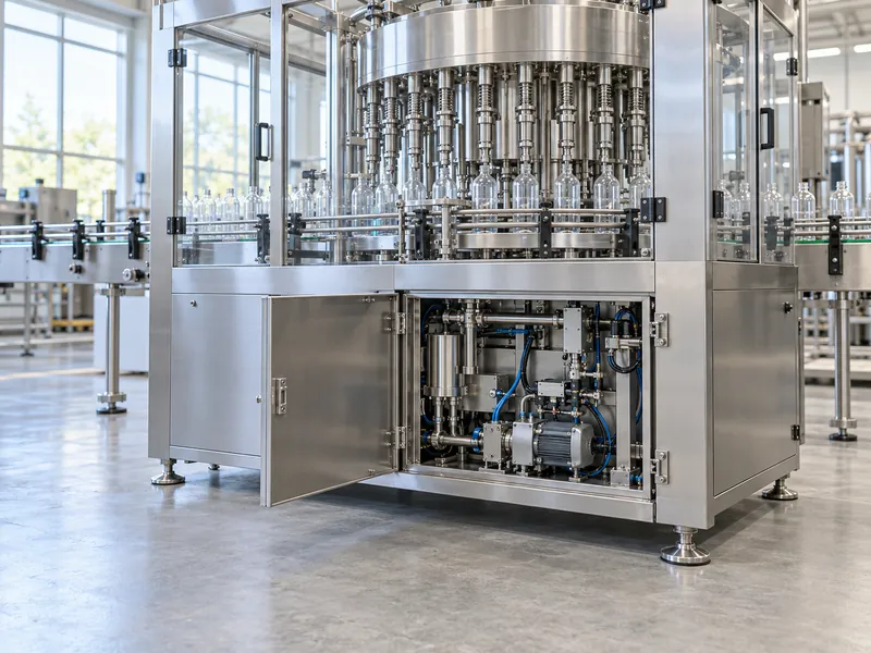
A monoblock filler needs space for its installed footprint, opened guards, routine operation, maintenance removal, format-part handling, and utility connections. It also needs a workable delivery and installation route. There is no reliable universal clearance that can be added to every machine: request a task-based layout for the exact model and review it against the factory’s access requirements.
The compact arrangement of rinsing, filling, and capping can reduce transfer equipment, but it does not remove the need to service those functions. A drawing showing only the closed enclosure can underestimate the space the line will occupy in daily use. Treat access as part of the machine specification.
Which Dimensions Should the Supplier Provide?
Request an approved general arrangement drawing with the machine footprint, overall height, conveyor interfaces, support points, and service connections. Add the swing or slide envelope of every access door and removable panel. Show the location and working face of the control cabinet and operator interface.
Ask for a separate maintenance envelope where components extend beyond the normal enclosure during removal. This may include motors, pumps, filling assemblies, capping heads, or lifting equipment, depending on the design. A door opening is useful only if the intended service task can be completed through it.
- Show closed-machine dimensions and access envelopes separately.
- Locate operator positions and normal material replenishment points.
- Identify component withdrawal paths and lifting requirements.
- Include conveyor elevations and transfer geometry.
- Mark utility, drainage, and cabinet connection locations.
Use these details when comparing monoblock filling machine options. A smaller catalog footprint is not necessarily a smaller installed solution if its service access extends into another part of the line.
How Should Routine Operating Space Be Planned?
Map the tasks performed during a normal shift: starting production, inspecting bottles, replenishing caps, responding to alarms, collecting samples, and removing rejected containers. The operator needs a clear route between these points. Locate carts and supplies so they do not occupy that route during production.
Check the operator’s view of the critical transfer areas and the control display. An interface that is physically accessible but faces away from the relevant machine section can make fault recovery awkward. Review the proposed arrangement with the people who will operate it.
Include the largest normal package and the actual replenishment method. A cap hopper filled by a mobile aid needs a different approach from one supplied automatically. Record the cart or lifting-aid dimensions instead of assuming the person alone defines the required space.
What Space Is Needed for Format Changes?
Place the format-parts trolley where operators can exchange components without crossing a busy transport route. Allow space for both the outgoing and incoming set. The temporary location of removed parts matters because the changeover occurs while the machine is open.
Check the path of large starwheels, curved guides, and bottle supports through the access opening. Confirm whether any component requires two-person handling or a lifting aid. Include the aid’s approach and operating envelope in the layout review.
Mark a clean storage location for parts awaiting installation. Do not let a nominal service aisle become the permanent home for tools, empty containers, and spare wheels. Once that happens, the drawing no longer represents the usable access on the floor.
How Do You Define Maintenance Clearance?
Ask the supplier to demonstrate representative maintenance tasks on the proposed machine or an equivalent arrangement. Review removal of common wear parts and at least one larger assembly. Record the tools, working posture, component path, and clearance needed for the task.
Distinguish frequent inspection access from occasional major overhaul access. Some major work may use a planned temporary area, provided the plant can actually make it available. Keep the conditions for that arrangement explicit rather than assuming neighboring equipment can always be moved.
| Space Category | What Must Fit | Typical Evidence |
| Machine footprint | Frame and closed enclosure | Approved general arrangement |
| Operating access | Operator and routine supplies | Shift-task walkthrough |
| Format change | Parts trolley and removed components | Changeover demonstration |
| Maintenance | Tools, withdrawal path, lifting aid | Service-task review |
| Installation route | Shipping module and handling equipment | Route survey and lifting plan |

What About Electrical Cabinets and Utilities?
Locate electrical cabinets so qualified personnel can perform the required work with the specified access and isolation arrangements. Apply the relevant local requirements through the plant’s engineering team. Do not infer electrical working clearances from the width of a nearby pedestrian aisle.
Show product piping, rinse supply, compressed air, cleaning connections, and drainage in the same coordinated layout. Pipes and trays installed later can obstruct a guard or component withdrawal path. Resolve these conflicts before fabrication rather than relying on field rerouting.
Provide access to valves, filters, instruments, and connection points that need inspection or service. A service point behind the machine may be acceptable only if the final installation leaves a suitable route to it. Confirm hose storage and connection handling where temporary cleaning hoses are used.
How Should Drainage and Floor Conditions Be Reviewed?
Check the floor loading, support arrangement, anchoring requirements, and finished elevations with the machine supplier and site engineer. Provide information about slopes, pits, and existing drainage channels. Leveling provisions cannot be assumed to compensate for any floor condition.
Arrange drains to collect expected discharges without creating standing water around normal working positions. Review cleaning access beneath and around the frame. Avoid placing a critical support or maintenance position where the facility cannot keep it accessible and clean.
Consider the path of washdown water and the location of adjacent equipment. A compact layout should not force cleaning runoff across a clean container route or into an unsuitable cabinet area. The correct solution depends on the machine’s protection rating and the plant cleaning method.
Which Height and Overhead Conflicts Matter?
Compare the installed height with ceiling services, beams, ducts, and lighting. Include any top-opening cover, cap-feed equipment, or raised component during maintenance. The tallest shipping module may differ from the tallest installed configuration.
If a lifting device is required, review the available hook height and the travel path of the suspended component. Confirm the capacity and intended lifting points through the approved handling plan. Space above the enclosure is useful only if the lifting operation can be performed as designed.
Keep overhead services outside the agreed maintenance envelope where practical. If a removable service section is proposed, document the extra work and isolation required. The cost of repeated disconnection should be visible during layout approval.
How Do You Check the Delivery Route?
Use the supplier’s transport drawing and handling instructions to plan the incoming move. Check each doorway and change of direction against the shipped module, its packaging, and the selected handling equipment; have the site team confirm the supporting surfaces and overhead envelope. Resolve any route restriction before fixing the delivery arrangement.
Check the handling equipment’s dimensions and turning needs as well as the machine itself. A module that fits through a door may still be impossible to position with the selected forklift or rigging arrangement. Agree which party supplies unloading, internal transport, and final placement.
Where dismantling is proposed, confirm that it is approved and identify who will reassemble and verify the machine. Do not assume guards, pipework, or precision-aligned sections can be removed simply to make an unsuitable route work. Resolve the route before shipment.
How Can Future Expansion Be Included?
Identify likely additions such as an inspection device, a cap elevator, or a different conveyor arrangement. Reserve a defined connection area when that expansion is part of the project plan. Avoid calling an occupied service aisle future production space, because it already has a necessary operating function.
Check whether the existing machine can be serviced while the proposed addition remains installed. A new cabinet or inspection tunnel may fit beside the frame yet block access to a drive or drain tray. Ask for an updated combined drawing before approving the additional equipment.
Document which reserved areas may be used temporarily and which must remain permanently clear. This helps the plant distinguish genuine expansion capacity from the access needed to keep the current filler working. Review the distinction again when the production mix or maintenance strategy changes.
How Should the Final Layout Be Approved?
Review the drawing with production, maintenance, hygiene, utilities, and installation representatives. Walk through normal operation, a format change, cleaning, and a major service task. Use floor markings or a scaled mockup where a tight arrangement is difficult to judge on paper.
Freeze the accepted layout revision and record any remaining site assumptions. Recheck access when a conveyor, cabinet, drain, or auxiliary device changes position. Small interface changes can consume the clearance that made the original layout workable.
To develop an installation plan, send Brenu your floor plan and access constraints. Request the machine’s operating and service envelopes together with shipping details so the installation can be evaluated as a complete working arrangement.